Thermal sensing structure and insulating structure of thermal sensing circuit

a technology of thermal sensing circuit and insulating structure, which is applied in the direction of thermometer details, instruments, heat measurement, etc., can solve the problems of large structure, many man-hours, and difficulty in connecting a plurality of thermal sensors, so as to prevent the expansion of the insulating resin mold fluid

Active Publication Date: 2010-08-05
YAZAKI CORP
View PDF14 Cites 18 Cited by
  • Summary
  • Abstract
  • Description
  • Claims
  • Application Information

AI Technical Summary

Benefits of technology

[0043]According to the above, in the resistless part, the remaining part (mainly solder-connecting part) of the circuit which is not covered with the insulating resin mold is secondly covered with the printed insulating film. The printed insulating film is formed simultaneously with respect to a p...

Problems solved by technology

However, owing to an abnormal energization or temperature rise, the PTC device becomes several dozen ohm resistor in a short time, and returns to an original resistor when an outside environment returns to a normal condition.
However, in the conventional thermal sensing structure, when a hard circuit board 42 is used, the structure becomes large and expensive.
Further, when using the lead wires 51 (including a case th...

Method used


Image

  • Thermal sensing structure and insulating structure of thermal sensing circuit
  • Thermal sensing structure and insulating structure of thermal sensing circuit
  • Thermal sensing structure and insulating structure of thermal sensing circuit

Examples


Embodiment Construction

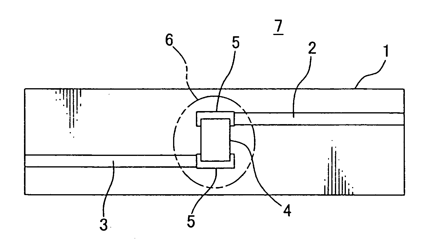
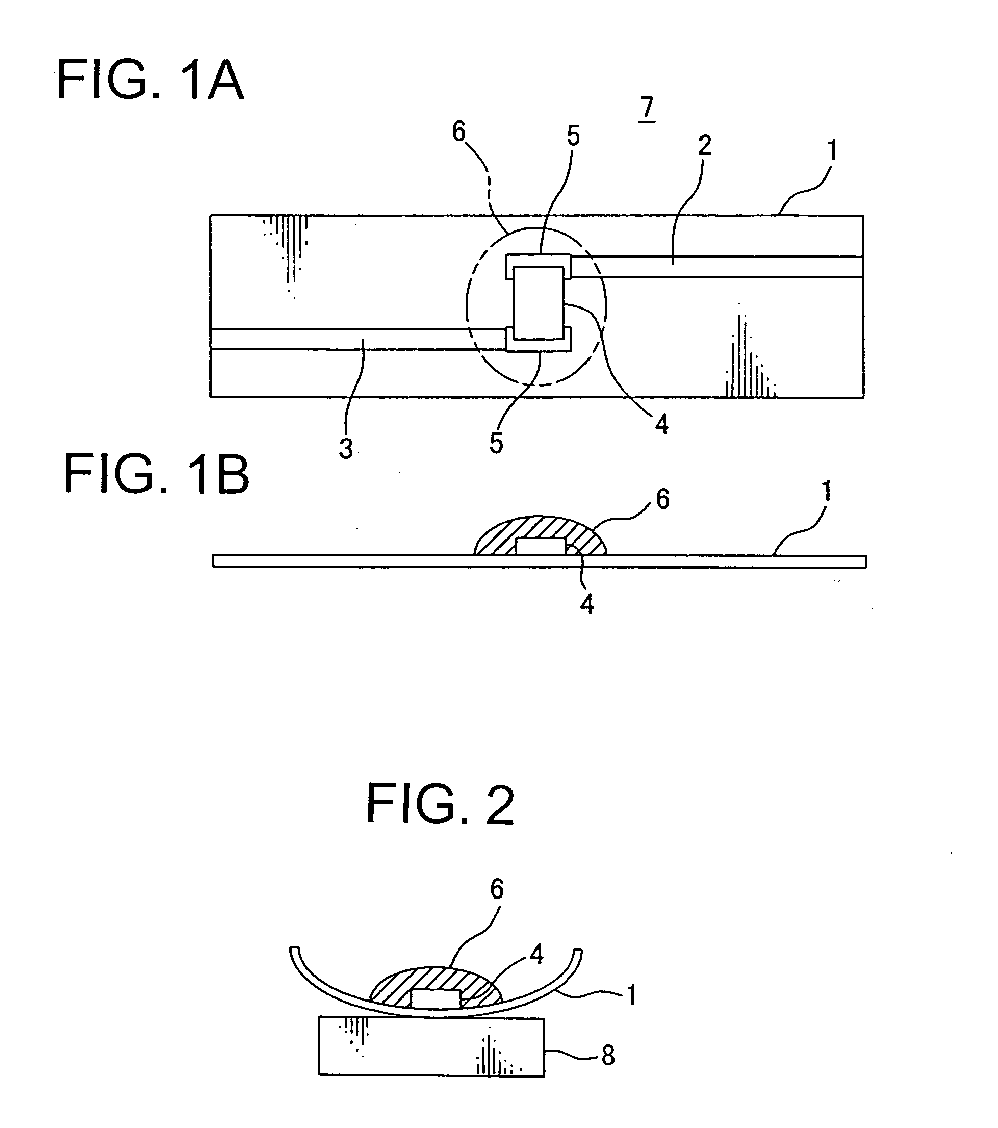
[0065]FIGS. 1A to 2 show an embodiment of a thermal sensing structure according to the present invention.

[0066]As shown in FIG. 1A, this thermal sensing structure is characterized by that two thin-foil-shaped metallic flexible circuits 2, 3 are formed on a surface (upper wall) of a flexible insulating sheet 1, a thermal sensor 4 is connected to two circuits 2, 3 (two circuits 2, 3 are connected to each other with the thermal sensor 4), and as shown in FIG. 1B, the thermal sensor 4 and connecting parts 5 are covered with an elastic insulating resin 6 by potting.

[0067]Preferably, the circuits 2, 3 are formed on the insulating sheet 1 by printing. Preferably, the circuits 2, 3 on the insulating sheet 1 are covered with an insulating film except the thermal sensor 4 and its neighbor (potting part 6). It is possible that the circuits 2, 3 are covered with an upper insulating sheet (preferably as thin as possible, because of flexibility) similar to the insulating sheet 1 instead of this i...


PUM


Abstract

Flexible circuits 2, 3 are formed on a flexible insulating sheet 1. A thermal sensor 4 is connected between the circuits 2, 3. The thermal sensor 4 and connecting parts 5 are integrally covered with an elastic insulating resin 6. While the insulating sheet 1 is bent together with the insulating resin 6, the thermal sensor 4 is pushed onto an object to be sensed 8 via the insulating sheet 1. A plurality of thermal sensors 4 are connected in series in a longitudinal direction of the insulating sheet 1. The insulating resin 6 covers the thermal sensors 4 and the connecting parts 5.

Description

CROSS REFERENCE TO RELATED APPLICATIONS[0001]This application is on the basis of Japanese Patent Application No. 2009-021120 and No. 2009-028412, the contents of which are hereby incorporated by reference.BACKGROUND OF THE INVENTION[0002]1. Field of the Invention[0003]The present invention relates to a thermal sensing structure for sensing temperature of, for example, a battery of an electric vehicle, and relates to an insulating structure of a thermal sensing circuit for sensing temperature of, for example, a battery of an electric vehicle.[0004]2. Description of the Related Art[0005]FIG. 6 shows an embodiment of a conventional thermal sensing structure (See Patent Document 1).[0006]In this structure, a circuit board 42 is arranged in an insulating synthetic resin made case 41. A thermal sensor 43 such as a thermistor is connected to the circuit board 42. The thermal sensor 43 is received in a recess 44 at an inside of the case 41. The recess 44 is filled with resin material 45. Th...

Claims


Application Information

Patent Timeline
IPC IPC(8): G01K1/08G01K1/00
CPCG01K1/08G01K13/10G01K7/16G01K1/14
Inventor ISHIKAWA, SATOSHIYAMAMOTO, SUSUMU
Owner YAZAKI CORP
Why Eureka
Try Eureka