Eureka AIR delivers breakthrough ideas for toughest innovation challenges, trusted by R&D personnel around the world.

Drill for sinus membrane lift

Active Publication Date: 2010-08-05
HEO YOUNG KU
View PDF21 Cites 18 Cited by
  • Summary
  • Abstract
  • Description
  • Claims
  • Application Information

AI Technical Summary

Benefits of technology

[0030]In the drill for sinus membrane lift of the present invention, the front end of the head is configured to come into face contact with the sinus membrane over a wide area in order to prevent the sinus membrane from being torn or damaged even if the head completely penetrates the maxilla and contacts the sinus membrane. As a result, the safety of the procedure can be better ensured and the procedure time can be greatly reduced.
[0031]Moreover, the depth of drilling can be limited by the stopper fitted onto the outer circumference of the body, thereby ensuring the safety of the procedure. The simple structure makes use thereof and management easier and enables mass production so that products can be standardized and economically distributed.

Problems solved by technology

The drilling of the alveolar bone is a very important procedure, which takes a long time and is difficult to perform.
A considerable number of patients have an oral structure which makes it difficult to perform the implant surgery.
However, negatives come from the facts that since the dentist cannot directly see the sinus membrane, he / she has to perform surgery very carefully, checking the membrane with X-ray images, which is time-consuming, thereby prolonging the surgery, and also the patient experiences severe discomfort due to the tapping performed during the surgery.
However, the method also has a problem in that the surgery itself is difficult to perform, and a larger valve should be provided, so that severe edema may occur after the surgery.
Since there are no means for preventing the drill blades from contacting the sinus membrane, there is a high risk that the sinus membrane can be torn or damaged by the drill blades.
However, in the conventional drill for sinus membrane lift, the protrusion member is integrally provided to the outer circumference of the tubular body, thereby reducing an effective drilling area.
Further, since the drill has a sophisticated construction, it is difficult to fabricate the drill or disassemble / assemble the drill for sterilization after surgery.
In particular, efficient drilling is difficult since the tubular body acting as a drilling component is supported by the spring.
Further, there is a risk that the sinus membrane may be damaged by a sharp front edge of the protrusion member.
However, this approach has drawbacks in that too much time is spent to drill the bone and there is no measure to control the depth to which the drill is inserted into the maxillary sinus.
A thick compact bone takes too much time for drilling, which is somewhat worrisome.
Further, there is a risk that a surgeon may apply an excessive force so excessively that the drill can be pushed into the maxillary sinus, thereby tearing or damaging the sinus membrane.

Method used


Image

  • Drill for sinus membrane lift
  • Drill for sinus membrane lift
  • Drill for sinus membrane lift

Examples


first embodiment

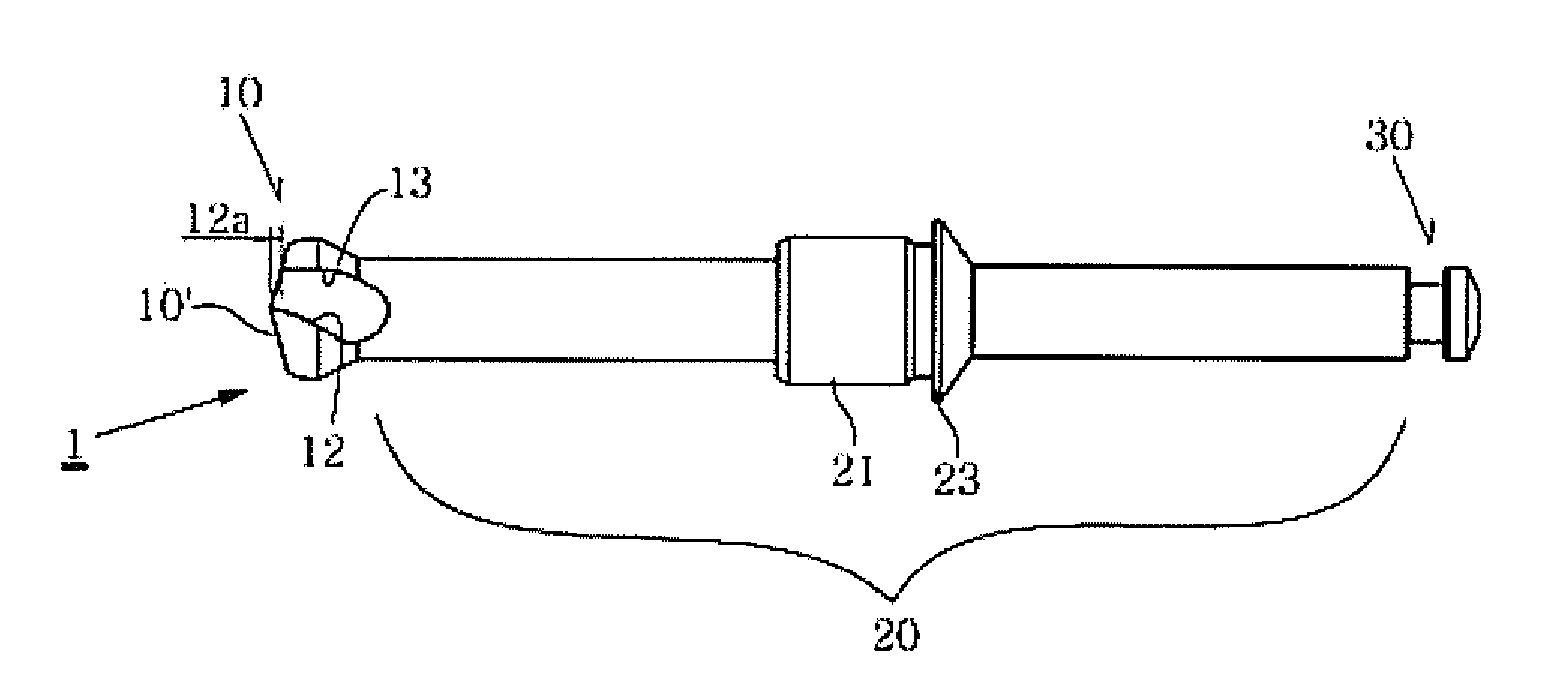
[0062]The drill for sinus membrane lift 1 of this embodiment has a similar construction to that of the first embodiment as described above. Herein, the same components will be designated with the same reference numerals and will not be described in detail.

[0063]As shown in the drawings, characteristic features of this embodiment are that the first inside wall 12 and the second inside wall 13 are directly connected to each other unlike in the first embodiment. Specifically, the first and second inside walls 12 and 13 run parallel to each other and then are connected to each other at an acute angle.

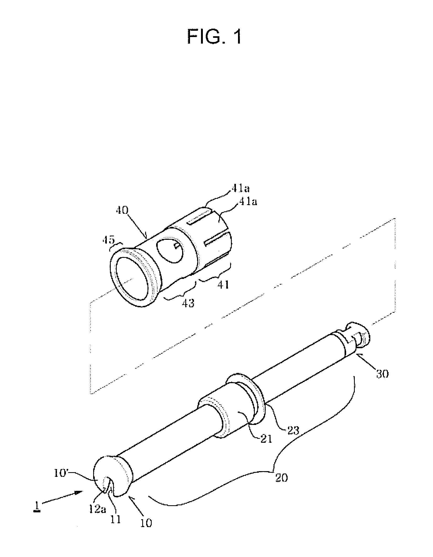
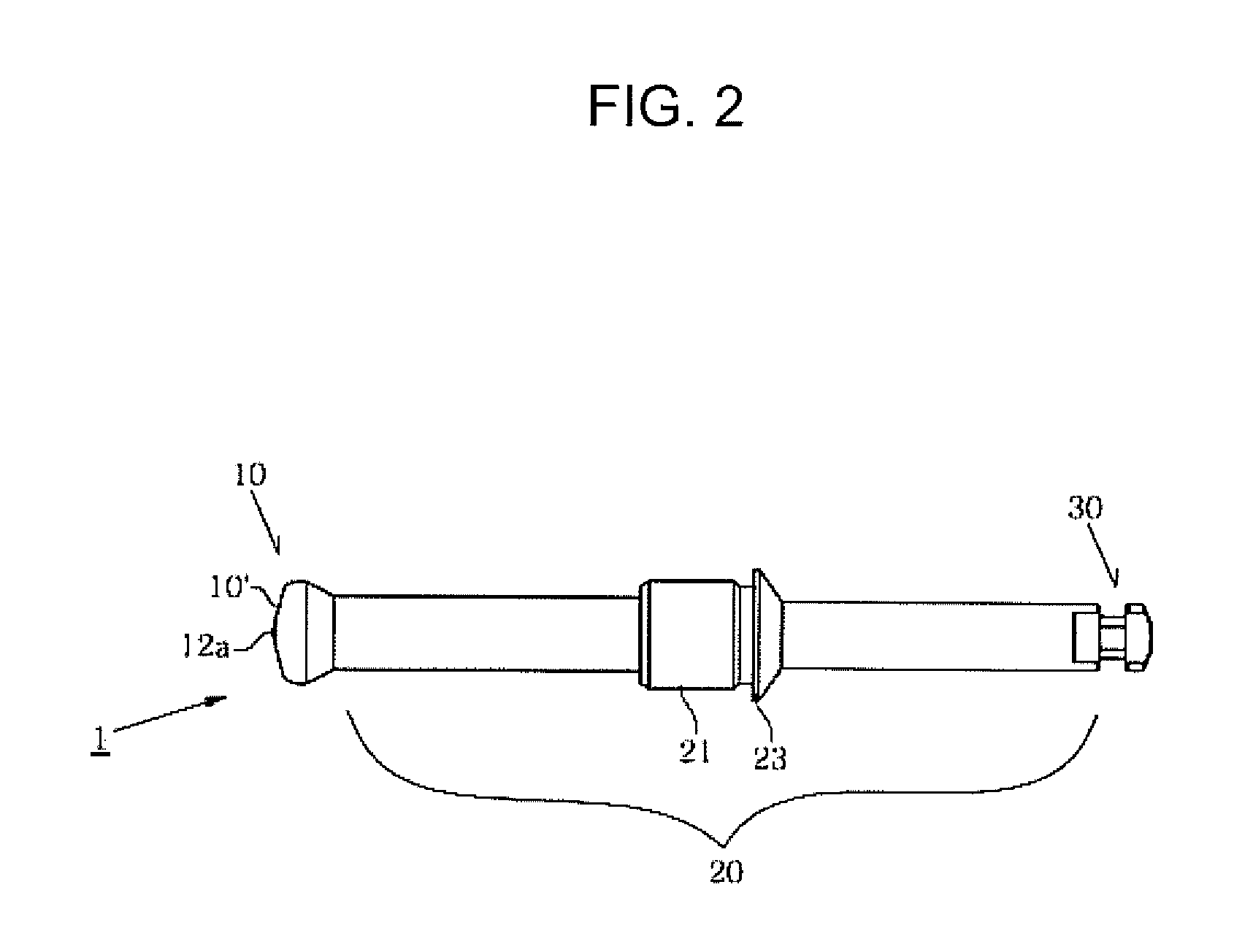
[0064]FIGS. 13 to 18 illustrate a drill for sinus membrane lift according to a third embodiment of the present invention, which is designed to maintain bone fragments as well as minimize any perforation of the membrane. In these drawings, FIG. 13 is a perspective view illustrating the first embodiment, FIG. 14 is a plan view of FIG. 13 as viewed from above, FIG. 15 is a front elevational vi...

second embodiment

[0072]The drill for sinus membrane lift 1 of this embodiment has a similar construction to that of the second embodiment as described above. Herein, the same components will be designated with the same reference numerals and will not be described in detail.

[0073]As shown in the drawings, this embodiment proposes two bone-maintaining areas 11 as characteristic features, which are spaced apart from each other with a uniform interval.

[0074]In the bone-maintaining areas 11, the first inside wall 12 and the second inside wall 13 are arranged opposite each other and are connected to each other at an acute angle.

[0075]Further, in a pair of the bone-maintaining areas 11, one of the two bone-maintaining areas can preferably include an axis so as to effectively drill the maxilla.

[0076]FIGS. 31 to 36 illustrate a drill for sinus membrane lift according to a sixth embodiment of the present invention, in which FIG. 31 is a perspective view illustrating the first embodiment, FIG. 32 is a plan vie...

third embodiment

[0077]The drill for sinus membrane lift 1 of this embodiment has a similar construction to that of the third embodiment as described above. Herein, the same components will be designated with the same reference numerals and will not be described in detail.

[0078]While the drill for sinus membrane lift 1 as the characteristic feature of this embodiment is similar to that of the third embodiment, this embodiment proposes two bone-maintaining areas 11 to be spaced apart from each other by a uniform interval as shown in the drawings.

[0079]The respective bone-maintaining areas 11 are provided in the form of through holes, and one of the bone-maintaining areas 11 can preferably include an axis so as to allow uniform and effective drilling of the maxilla.


PUM


Abstract

A drill for sinus membrane lift includes a contact surface for coming in face contact with sinus membrane, the contact surface having a curved periphery, and a bone-maintaining area connected to the contact surface for storing and discharging drilled bone fragments. The bone-maintaining area includes a first inside wall and a second inside wall connected to the first inside wall, the first inside wall oriented in a drilling direction, and the second inside wall opposite the first inside wall. The first inside wall has a drilling surface and is formed higher than the second inside wall so that the drilling surface is exposed in the drilling direction. The front end of the head comes into face contact with the sinus membrane at a wide area to prevent the sinus membrane from being torn or damaged even if the head completely penetrates the maxilla and contacts the sinus membrane.

Description

TECHNICAL FIELD[0001]The present invention relates to a drill used in a procedure for installing a surgical implant, and more particularly, to a drill for sinus membrane lift, which is designed to safely and precisely drill the maxilla or the upper jawbone, thereby ensuring safety and convenience in the procedure.BACKGROUND ART[0002]In general, a dental implant is an artificial tooth root that replaces a missing tooth of a patient. The dental implant is installed and incorporated to a toothless site of the alveolar bone and then is fixed to the alveolar bone in order to replace a missing tooth root and recover the original function of the tooth. Here, the dental implant is made of a biocompatible alloy of for example titanium.[0003]A dental implant procedure generally involves several surgeries such as incising and peeling the soft tissue and drilling the bone for installation of the implant, installing the implant, and constructing an upper prosthesis. The surgeries for incising an...

Claims


Application Information

Patent Timeline
IPC IPC(8): A61C1/08
CPCA61B2019/306A61C8/0092A61C8/0089A61C3/02A61B2090/036A61C8/00
Inventor HEO, YOUNG KU
Owner HEO YOUNG KU
Why Eureka
Eureka Blog
Learn More