Ultrasonic diagnostic apparatus, ultrasonic image processing apparatus, medical image diagnostic apparatus, medical image processing apparatus, ultrasonic image processing method, and medical image processing method

a diagnostic apparatus and ultrasonic technology, applied in ultrasonic/sonic/infrasonic diagnostics, ultrasonic diagnostic equipment, medical image diagnostic equipment, etc., can solve the problems of inability to accurately evaluate the radial strain rs (t) for each endocardium and epicardium, affecting the accuracy of movement information, and deteriorating, etc., to achieve accurate evaluation of radial strain

Active Publication Date: 2010-08-05
TOSHIBA MEDICAL SYST CORP
View PDF14 Cites 32 Cited by
  • Summary
  • Abstract
  • Description
  • Claims
  • Application Information

AI Technical Summary

Benefits of technology

[0020]The present invention is contrived in consideration of the above-described circumstances, and an object of the invention is to provide an ultrasonic diagnostic apparatus, an ultrasonic image processing apparatus, a medical image diag

Problems solved by technology

At this time, when low-correlation pattern matching occurs, the accuracy of the movement information is influenced and deteriorated because the number of the highly precise remained movement vectors at the closest position becomes small, and hence the tracking process may easily fail.
In such an analysis, in the known method, a problem arises in that the radial strain RS (t) for each of the endocardium an

Method used


Image

  • Ultrasonic diagnostic apparatus, ultrasonic image processing apparatus, medical image diagnostic apparatus, medical image processing apparatus, ultrasonic image processing method, and medical image processing method
  • Ultrasonic diagnostic apparatus, ultrasonic image processing apparatus, medical image diagnostic apparatus, medical image processing apparatus, ultrasonic image processing method, and medical image processing method
  • Ultrasonic diagnostic apparatus, ultrasonic image processing apparatus, medical image diagnostic apparatus, medical image processing apparatus, ultrasonic image processing method, and medical image processing method

Examples


first embodiment

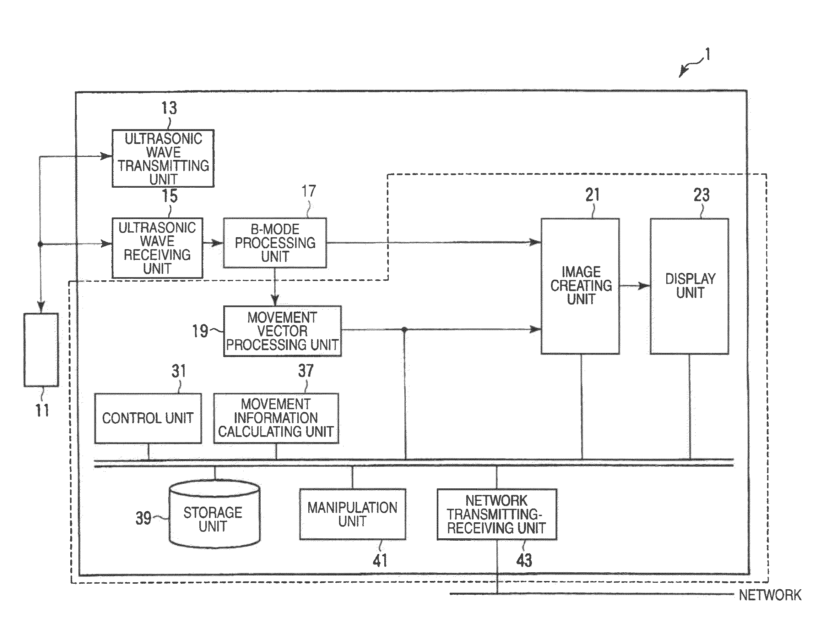
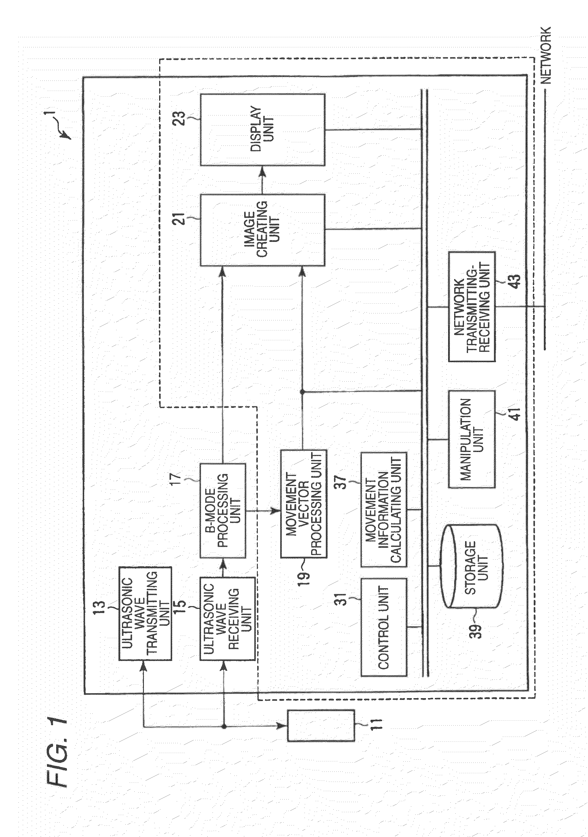
[0042]Hereinafter, a first embodiment of the invention will be described with reference to the drawings. In the following description, the same reference numerals will be given to the constituents substantially having the same function and configuration, and repetitive description thereof will be only made if necessary.

[0043]In addition, in the first embodiment, a case will be described in which the technical spirit of the invention is applied to an ultrasonic diagnostic apparatus. However, the invention is not limited thereto, and the technical spirit of the invention may be applied to an ultrasonic image processing apparatus using a workstation, a personal computer, and the like.

[0044]Further, the functions realized by the constituents according to the first embodiment, and particularly, the functions realized by a movement vector processing unit 19, an image creating unit 21, and a movement information calculating unit 37 may be also realized in such a manner that a software prog...

second embodiment

[0080]Next, a second embodiment of the invention will be described. In the first embodiment, “the normal retracking process from the ED1 to the ES” of the tracking point of the middle layer and the contours of the endocardium and the epicardium rearranged at the ED1 is performed, and then the normal tracking process (ST process) is performed until the ED2. On the contrary, in the second embodiment, instead of the normal retracking process from the ED1 to the ES, the movement information of the inner and outer cardiac walls is accurately created and evaluated in such a manner that “the initial reverse tracking process of plural middle layer path candidates is performed from the ES to the ED1 and the path passing through the tracking points on the middle layer and the contours of the endocardium and the epicardium rearranged at the ED1 is searched”.

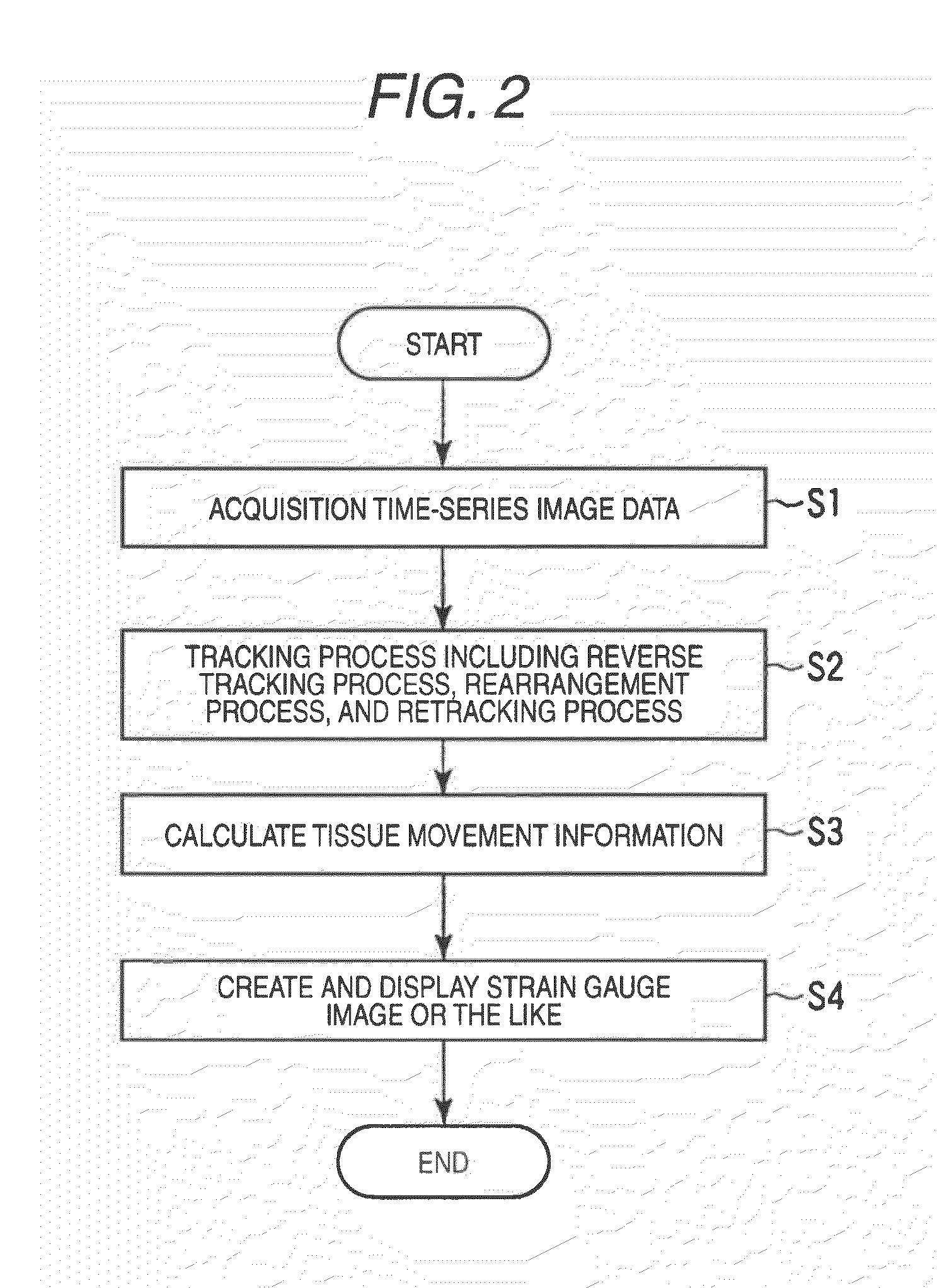
[0081]The second embodiment is different from the first embodiment in that the contents in Step S2 of FIG. 2 are different. Hereinafter, t...

third embodiment

[0090]In the first and second embodiments, basically, the application example in the case of the two-dimensional image is described. However, the technical spirit of the invention may be applied to the case where the three-dimensional ST process is performed on the three-dimensional image. Here, the case where the three-dimensional ST process is performed on the three-dimensional image is disclosed in, for example, Japanese Unexamined Patent Application Publication No. 2003-250804. In addition, in this case, the display example of the strain gauge in which the endocardium and the epicardium are separated is disclosed in Japanese Patent Application No. 2008-160744 and the like. Accordingly, even in the case where the three-dimensional ST process is performed on the three-dimensional image so as to perform the separate analysis of the endocardium and the epicardium by expanding the concept shown in the first embodiment or the second embodiment to three dimensions, it is possible to re...


PUM


Abstract

In the case where a tracking process of a moving tissue performing a contraction movement and an expansion movement and represented by a cardiac wall is performed for one heartbeat from the ED1 to the ED2, a contour position (tracking point) initially set at the ES (End-Systole) is tracked until ED1 in accordance with movement information, the tracking point is rearranged and a position of a middle layer is set at the ED (End-Diastole), the rearranged tracking point including the position of the middle layer is tracked in accordance with the movement information already obtained, and then the tracking point is further tracked in the normal direction until the ED2. Alternatively, an initial reverse tracking process is performed from the ES to the ED1 by using plural middle layer path candidates, and a path passing through the tracking point existing on the middle layer or contours of inner and outer layers and rearranged at the ED1 is searched, thereby accurately creating and evaluating movement information of each of an endocardium and an epicardium of a cardiac wall.

Description

CROSS-REFERENCE TO RELATED APPLICATIONS[0001]This application is based upon and claims the benefit of priority from prior Japanese Patent Applications No. 2009-020678, filed Jan. 30, 2009; and No. 2009-274675, filed Dec. 2, 2009, the entire contents of both of which are incorporated herein by reference.BACKGROUND OF THE INVENTION[0002]1. Field of the Invention[0003]The present invention relates to an ultrasonic diagnostic apparatus capable of obtaining tissue movement information such as cardiac wall movement information, an ultrasonic image processing apparatus performing an image process by using the tissue movement information obtained by the ultrasonic diagnostic apparatus, a medical image diagnostic apparatus, a medical image processing apparatus, an ultrasonic image processing method, and a medical image processing method.[0004]2. Description of the Related Art[0005]In the ultrasonic diagnosis, a heartbeat or a fetus's movement state may be obtained in real time just by touchi...

Claims


Application Information

Patent Timeline
IPC IPC(8): A61B8/14G06K9/00
CPCA61B8/08A61B8/0883
Inventor ABE, YASUHIKOKAWAGISHI, TETSUYA
Owner TOSHIBA MEDICAL SYST CORP
Why Eureka
Try Eureka