Medical manipulator

Active Publication Date: 2010-08-05
KARL STORZ GMBH & CO KG
View PDF10 Cites 85 Cited by
  • Summary
  • Abstract
  • Description
  • Claims
  • Application Information

AI Technical Summary

Benefits of technology

[0015]It is an object of the present invention to provide a medical manipulator, which

Problems solved by technology

Forceps that have been available heretofore have only a few degrees of freedom, e.g., one degree of freedom, and are difficult to handle because they are movable only in limited directions for gripping and cutting tissues or for inserting suture needles, and require surgeon to be highly skilled when using them.
However, external forces applied to the distal-end working unit, as well as gripping forces applied by the distal-end working unit, are not transmitted to the master side of the master-slave remote control surgical robot.
If a sensation of force is to be available on the master side of the master-slave remote control surgical robot, then the

Method used


Image

  • Medical manipulator
  • Medical manipulator
  • Medical manipulator

Examples


Embodiment Construction

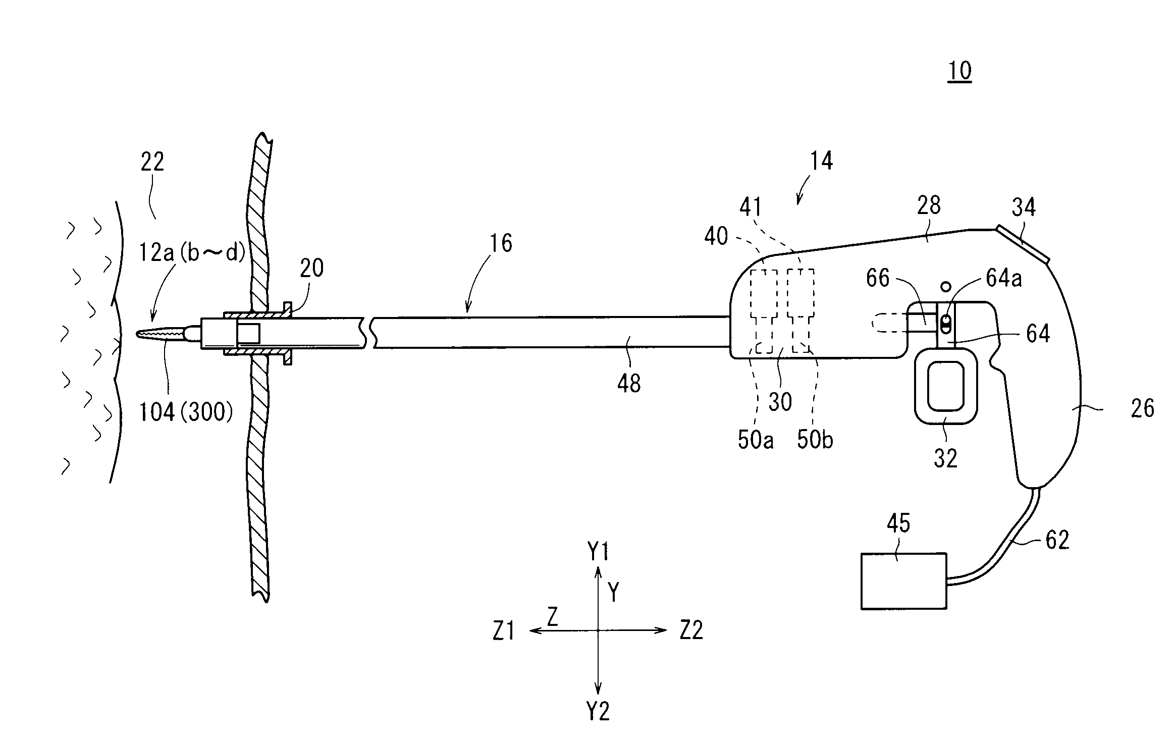
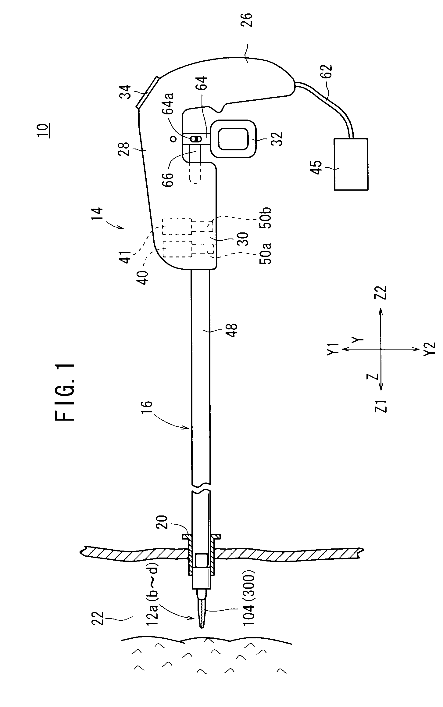
[0080]Medical manipulators according to embodiments of the present invention will be described below with reference to FIGS. 1 to 35.

[0081]As shown in FIG. 1, a medical manipulator 10 according to a first embodiment of the present invention serves as part of a medical manipulator system, and is electrically connected to a controller 45.

[0082]The controller 45, which electrically controls the medical manipulator 10, is connected by a connector to a cable 62, which extends from the lower end of a grip handle 26 of the medical manipulator 10. The controller 45 is capable of independently controlling a plurality of medical manipulators 10 at the same time, although the controller 45 also can control a single medical manipulator 10, as shown in FIG. 1.

[0083]The medical manipulator 10 includes a distal-end working unit 12a for gripping a portion of a living tissue, a curved needle, or the like, for performing a predetermined surgical treatment. The distal-end working unit 12a typically is...


PUM


Abstract

A medical manipulator includes a wire movable in opposite directions, a driven wire having both ends thereof connected to the wire, an end effector of a distal-end working unit, a transmitting member, a crescent driven member integral with the transmitting member, and a return pulley. The transmitting member, the crescent driven member, and the return pulley are successively arranged in this order from the proximal end of the medical manipulator. When the driven wire is moved in opposite directions, the transmitting member also moves in opposite directions. At this time, the crescent driven member moves toward the return pulley, and the proximal-end portion of the return pulley enters a cavity of the crescent driven member.

Description

CROSS-REFERENCE TO RELATED APPLICATION[0001]This application is based upon and claims the benefit of priority from Japanese Patent Applications No. 2009-022902 filed on Feb. 3, 2009 and No. 2009-078992 filed on Mar. 27, 2009, in the Japan Patent Office, of which the contents are incorporated herein by reference.BACKGROUND OF THE INVENTION[0002]1. Field of the Invention[0003]The present invention relates to a medical manipulator for use in laparoscopic surgery, for example.[0004]2. Description of the Related Art[0005]According to a laparoscopic surgical operation process, a certain number of small holes are opened in the abdominal region, for example, of a patient, and a flexible scope and manipulators or forceps are inserted into the holes. The surgeon performs a surgical operation on the patient with the manipulators or forceps while watching an image captured by the flexible scope and displayed on a display monitor. Since the laparoscopic surgical operation process does not requir...

Claims


Application Information

Patent Timeline
IPC IPC(8): A61B17/28
CPCA61B17/29A61B19/22A61B2017/00398A61B2019/2242A61B2017/2939A61B2017/2943A61B2019/2223A61B2017/2929A61B34/70A61B34/71A61B34/37
Inventor JINNO, MAKOTOIWAYOSHI, SHUNSUKE
Owner KARL STORZ GMBH & CO KG
Why Eureka
Try Eureka