
Intervertebral disc inserting device

a technology of inserting device and disc, which is applied in the field of inserting device of disc, can solve the problems of eroding facet joints, dehydration, disc flattening and/or bulging, etc., and achieve the effect of reducing segmental instability and eroding facet joints

Inactive Publication Date: 2010-08-05
YEUNG JEFFREY ERIC +1
View PDF5 Cites 8 Cited by
  • Summary
  • Abstract
  • Description
  • Claims
  • Application Information

AI Technical Summary

Benefits of technology

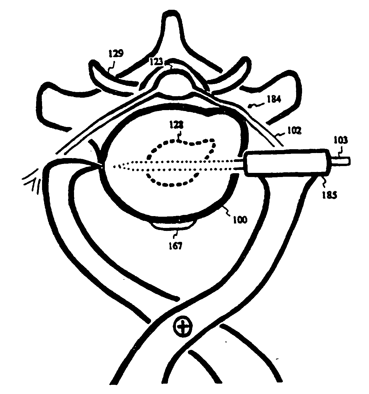
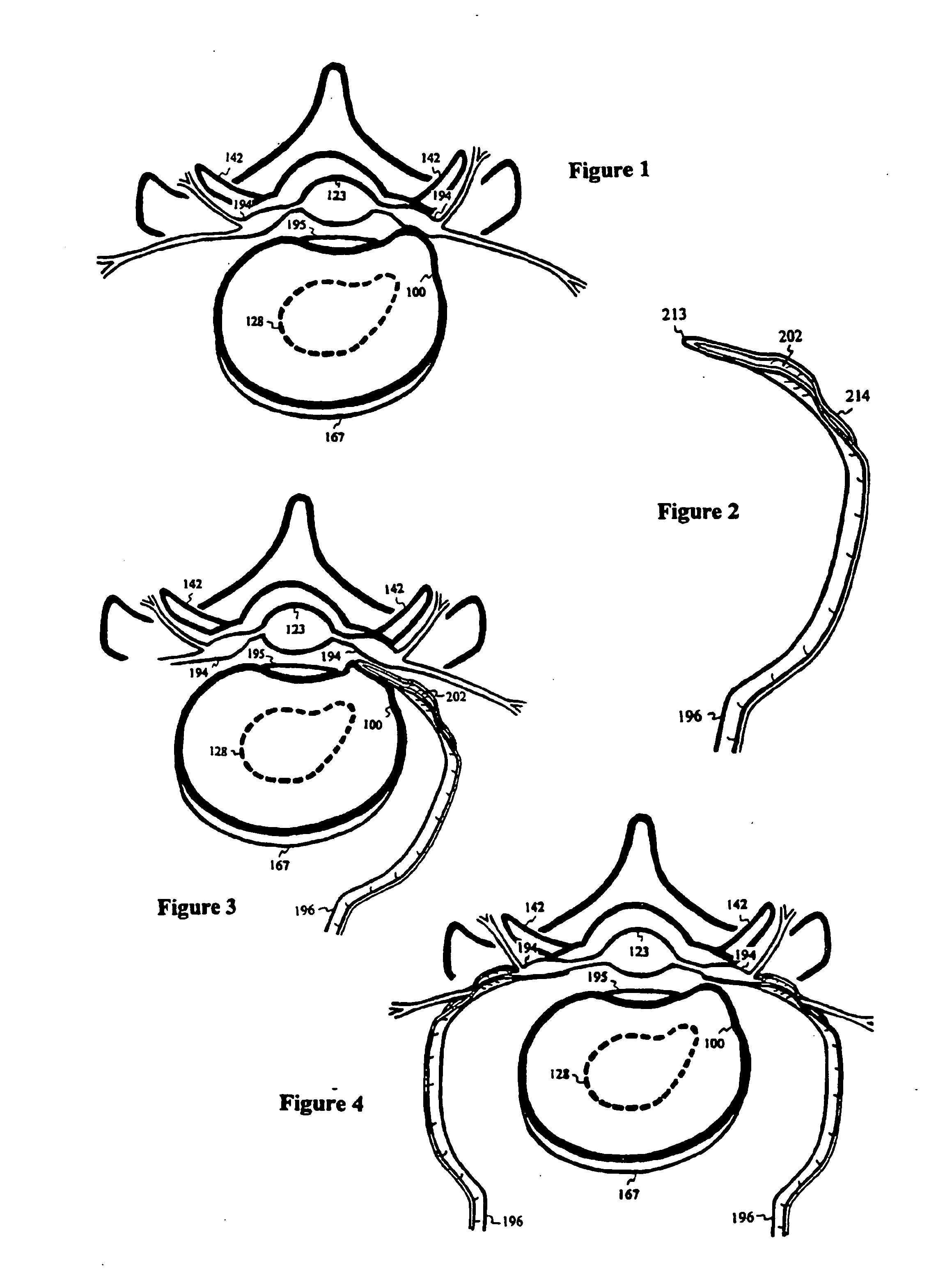
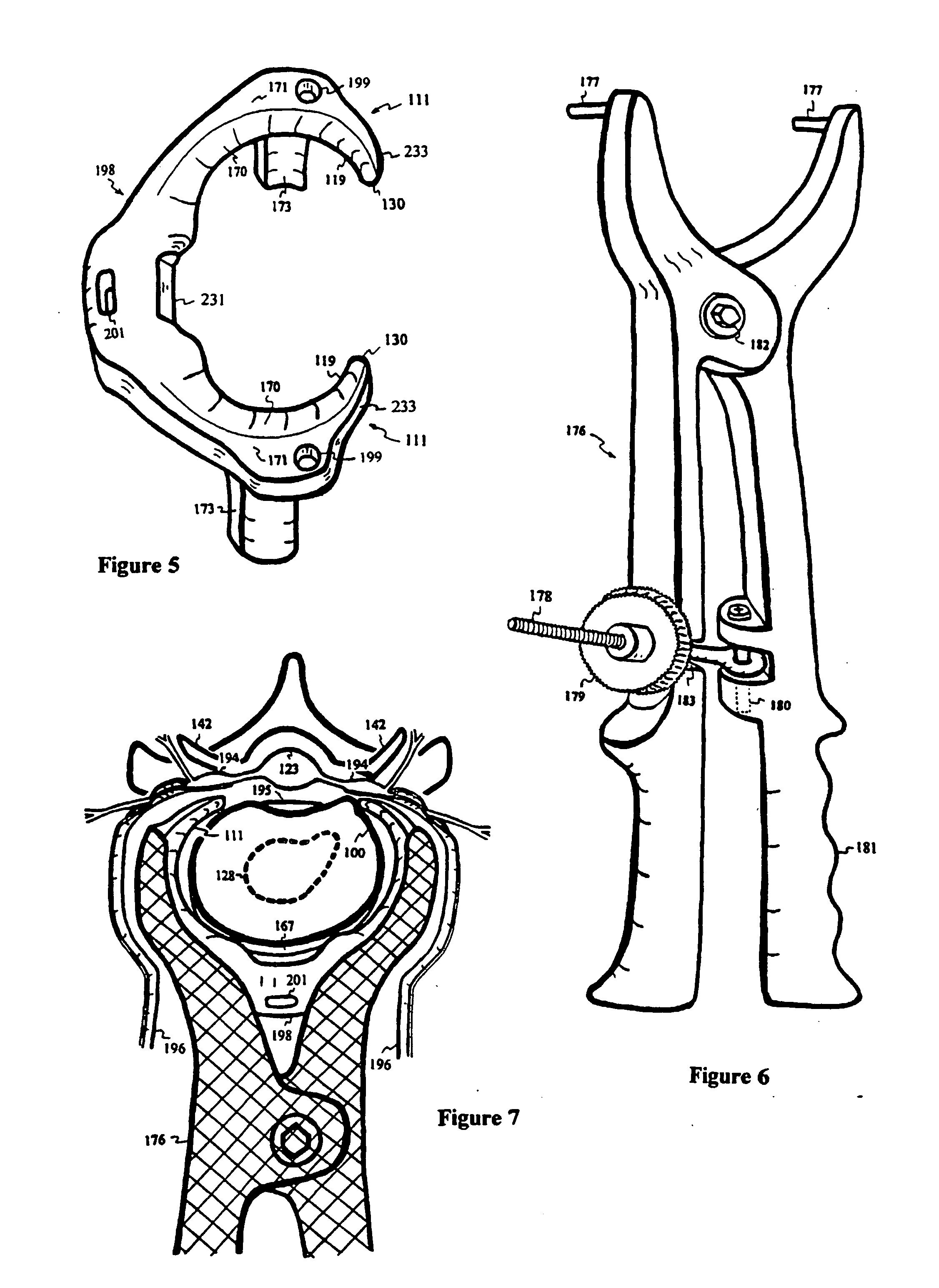
[0030]In this invention, a disc inserting device contains a horizontally oriented protrusion with superior and inferior plateaus for inserting into the degenerated disc to maintain or restore disc height. The horizontally oriented protrusion is adjoined to a vertically oriented concave bracket with screw holes for fastening the concave bracket to the vertebral bodies sandwiching the degenerated disc. Thereby, the disc height is restored and fortified to reduce segmental instability and erosion of facet joints for pain relief. Furthermore, by altering the slopes of the plateaus, thickness and depth of the protrusion, spinal stenosis, scoliosis, kyphosis, lordosis or spondylolisthesis can be corrected with the disc inserting device.REFERENCE NUMBER100Intervertebral disc101Tightening elements102Nerve103Trocar104Sleeve with windows105End-plate106Slit opening107Strut108Head of sleeve with window109Thread110Hole for screw or bolt111Disc compressor112Indented portion115Epiphysis116Bolt head117Stabilizer lumen118End of lift spring119Annulus contact surface120Hole for bolt121Lift spring122Supporting plate123Spinal cord124Delivery device125Coil spring126Pivoting means127Elastic fastening means128Nucleus pulposus129Facet joint130Tip of the compressor131Delivery capsule132Latch133Socket drive134Stabilizer135Lip of stabilizer139Bracket140Sacrum142Superior articular process143Inferior articular process159Vertebral body160Tissue ingrowth opening161Bolt162Nut163Washer164Indentation165Slit hole for bolt or screw167Anterior longitudinal ligament170Sloped surface171Plateau surface172Pivotal peg or screw173Stop176Widening tool177Clamp grabber178Lock screw of widening tool179Lock wheel of widening tool180Hinge of lock screw181Handle of widening tool182Pivotal joint of widening tool183Lock slot184Impingement of nerve185Trocar guide187Screw188Casing of compressor194Ventral / dorsal ramus nerve root195Posterior longitudinal ligament196Nerve shield198Clamp199Widening mount201Support mount202Trough on shield212Strap213Distal tip of the nerve shield214Open channel of nerve shield215Staple216Sinuvertebral nerve217Screw entry218Biodegradable sleeve220Trocar sleeve221Label showing direction of curvedtrocar223Trough or indentation of compressor224Bleeding sites225Lumen of sleeve with window226Screw head228Opening for socket or screw driver229Locking mechanism230Dilator231Indentation of disc clamp233Outer surface234Spinal fusion

Problems solved by technology

With limited nutrients within the avascular disc, the water-retaining proteoglycans begin to diminish, resulting in dehydration, flattening and / or bulging of the disc.
The flattened disc causes segmental instability, eroding the facet joints and causing pain.

Method used


Image

  • Intervertebral disc inserting device
  • Intervertebral disc inserting device
  • Intervertebral disc inserting device

Examples


Embodiment Construction

[0123]FIG. 1 depicts a common nerve 194 impingement from a protruded disc 100 at or near the narrow channel of the neuroforamen. For protection during disc 100 repair, a nerve shield 196 contains a thin and blunt distal tip 213 for reaching into or near the neuroforamen, a trough 202 to partially surround and protect the nerve 194 and an open channel 214 for the nerve 194 to exit from the trough 202. Through anterior or lateral incision, the nerve shield 196 is introduced by sliding over the bulging annulus of the disc 100, as shown in FIG. 3, to minimize potential damage to the ventral / dorsal ramus nerve root 194. The shield 196 is then gently pressed against the partially surrounded nerve 194. Similarly, another nerve shield 196 is used contralaterally to protect both nerves 194 existing from the neuroforamen, as shown in FIG. 4.

[0124]FIG. 5 shows an elastic intervertebral disc clamp 198 with an annular contact surface 119, a sloped surface 170, a plateau surface 171 and stops 173...


PUM


Abstract

With limited nutrients within the avascular disc, the water-retaining proteoglycans begin to diminish, resulting in dehydration, flattening and / or bulging of the disc. The flattened disc causes segmental instability, eroding the facet joints and causing pain.In this invention, a disc inserting device contains a horizontally oriented protrusion with superior and inferior plateaus for inserting into the degenerated disc to maintain or restore disc height. The horizontally oriented protrusion is adjoined to a vertically oriented concave bracket with screw holes for fastening the concave bracket to the vertebral bodies sandwiching the degenerated disc. Thereby, the disc height is restored and fortified to reduce segmental instability and erosion of facet joints for pain relief. Furthermore, by altering the slopes of the plateaus, thickness and depth of the protrusion, spinal stenosis, scoliosis, kyphosis, lordosis or spondylolisthesis can be corrected with the disc inserting device.

Description

CROSS REFERENCES[0001]This application is a continuation of U.S. Ser. No. 10 / 470,181, filed on Jul. 21, 2003 as the US national application of PCT / US2002 / 04301, filed on Feb. 13, 2002.[0002]This continuation application also claims priority of U.S. Provisional 60 / 268,666 filed on Feb. 13, 2001; U.S. Provisional 60 / 297,556 filed on Jun. 11, 2001; U.S. Provisional 60 / 310,131 filed on Aug. 3, 2001; U.S. Provisional 60 / 325,111 filed on Sep. 26, 2001; U.S. Provisional 60 / 330,260 filed on Oct. 17, 2001.FIELD OF INVENTION[0003]This invention relates to devices and methods for occupying and maintaining the intervertebral disc space by fastening the disc space inserting devices to one or more vertebral body to treat spine pain.BACKGROUND, EXISTING SURGICAL PRACTICES AND PRIOR INVENTIONS[0004]Low-back pain is one of the most prevalent, costly and debilitating ailments afflicting mankind. Seventy to eighty-five percent of all people have back pain at some time in their life. Symptoms are most ...

Claims


Application Information

Patent Timeline
Patent Type & Authority Applications(United States)
IPC IPC(8): A61B17/56A61B17/00A61B17/70A61F2/44
CPCA61B17/70A61F2002/4435A61B2017/00867A61B2017/00004
Inventor YEUNG, JEFFREY ERICYEUNG, TERESA T.
Owner YEUNG JEFFREY ERIC
Learn More