Safety Photoelectric Switch

a photoelectric switch and safety technology, applied in the direction of electric controllers, pulse techniques, instruments, etc., can solve the problems of interference among these optical scanning type photoelectric switches, undesirable cost for users, and the inability to arrange a plurality of photoelectric switches to ensure safety in this one danger area

Active Publication Date: 2010-08-05
KEYENCE
View PDF50 Cites 43 Cited by
  • Summary
  • Abstract
  • Description
  • Claims
  • Application Information

AI Technical Summary

Benefits of technology

[0012]According to the photoelectric switch of the present invention, since one photoelectric switch has a plurality of output systems capable of individually setting different safety functions or protection areas, it is possible to provide one device for rationally performing safety control on a plurality of danger sources without using the safety PLC as in the conventional case.
[0013]According to a preferred embodiment of the present invention, an inspection signal is superimposed on each output of the plurality of output systems at a different timing in a time-division manner. With the inspection signal superimposed, a failure can be sensed even when a short circuit occurs among safety outputs of the plurality of systems, so as to ensure the reliability of the safety control through use of an optical scanning type photoelectric switch.

Problems solved by technology

Although the safety PLC has versatility in allowing a user to perform programming to enable various controls, but from the viewpoint of safety verification, it is inconvenient in that another equipment is required for verifying a program made by the user.
Further, from another point of view, even supposing that a plurality of danger sources are present in one danger area, it makes no difference in the danger area being one, and arranging a plurality of photoelectric switches for ensuring safety in this one danger area is undesirable for the user in terms of cost.
Moreover, there is a problem specific to the optical scanning type photoelectric switch in that, since this optical scanning type photoelectric switch performs scanning over a broad range with light, in the case of arranging a plurality of optical scanning type photoelectric switches in one danger area, a problem of interference among these optical scanning type photoelectric switches may occur.
Although the interference problem can be solved naturally by adjustment of an installed position or a height of the optical scanning type photoelectric switch in its arrangement, it means that such adjustment leads to a matter of restriction concerning the arrangement of the optical scanning type photoelectric switch, and for example, a problem of one plane being not protectable at the same height takes place.

Method used


Image

  • Safety Photoelectric Switch
  • Safety Photoelectric Switch
  • Safety Photoelectric Switch

Examples


examples

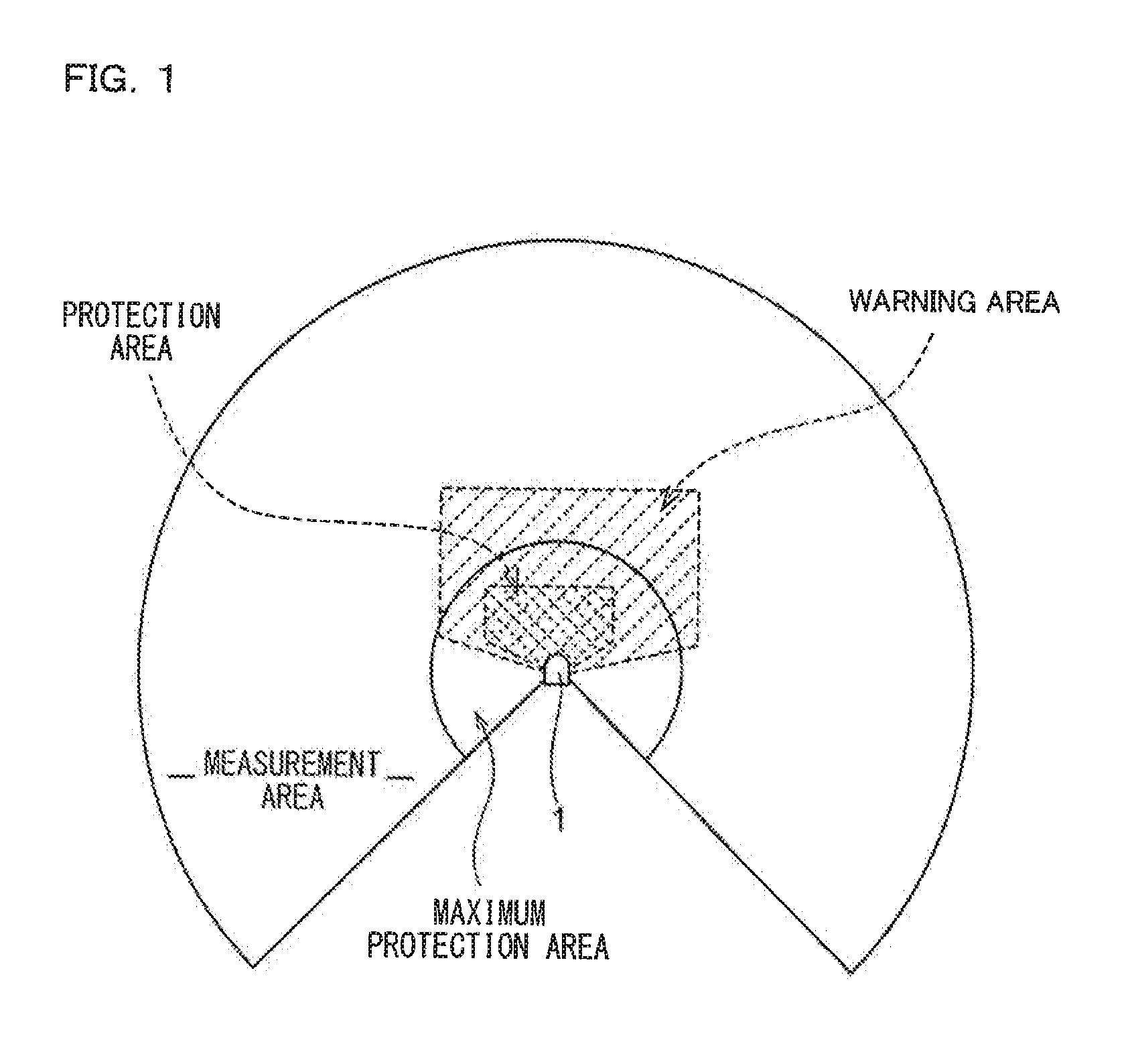
[0072]With reference to FIG. 1, as generalities, basic terms of an optical scanning type photoelectric switch: “measurement area”; “maximum protection area”; “warning area”; and “protection area”, are described. The “maximum protection area” means a region where objects having a variety of reflection factors from a low reflection factor object to a high reflection factor object, which are stipulated by the safety standard, are detectable by the optical scanning type photoelectric switch. The “measurement area” means a region where an object having a standard reflection factor is detectable by the optical scanning type photoelectric switch, and this “measurement area” completely includes the “maximum protection area”.

[0073]As is known, the optical scanning type photoelectric switch is used to two-dimensionally scan the maximum protection area with light such as laser light and monitor scanning light reflected from the maximum protection area, thereby to monitor safety inside the area...


PUM


Abstract

A photoelectric switch reduces a cost load of a user while ensuring its protection function inherent to safety equipment without impairing its safety function, and an optical scanning type photoelectric switch is provided with a muting function settable by the user, which is a function of temporarily invalidating sensing of part or the whole of a protection area, and is provided with two output systems, with respect to each of which the muting function is settable and on each output of which an inspection signal is superimposed at a different timing in a time-division manner.

Description

CROSS-REFERENCE TO RELATED APPLICATIONS[0001]The present application claims foreign priority based on Japanese Patent Application No. 2009-021043, filed Jan. 31, 2009, and No. 2009-021042, filed Jan. 31, 2009, the contents of which is incorporated herein by reference.BACKGROUND OF THE INVENTION[0002]1. Field of the Invention[0003]The present invention relates to a safety photoelectric switch.[0004]2. Description of the Background Art[0005]As seen in Japanese Patent Application Laid-Open No. H4-310890 and Japanese Patent Application Laid-Open No. H3-175390, an optical scanning type photoelectric switch is known which two-dimensionally performs scanning with light to detect an object while detecting a position of this object. As also referred to as a safety scanner, a safety laser scanner, and the like, this optical scanning type photoelectric switch provides a protection area around a machine, a robot or the like as a danger source, and outputs to the danger source a safety signal no...

Claims


Application Information

Patent Timeline
Patent Type & Authority Applications(United States)
IPC IPC(8): G05B9/02H03K17/78
CPCG01S7/4812G01S7/4817G01S7/497G05B9/02G01S17/42G01V8/14G01S17/026G01V8/18G01V8/20G01S17/04G01S7/4868G01S7/484G01S2007/4975
Inventor KAWABATA, SHINJIINOUE, TETSU
Owner KEYENCE
Why Eureka
Try Eureka