Signal processing apparatus and signal processing method

Active Publication Date: 2010-08-05
NEC CORP
View PDF2 Cites 24 Cited by
  • Summary
  • Abstract
  • Description
  • Claims
  • Application Information

AI Technical Summary

Benefits of technology

[0072]According to the present invention, the influence of a DC offset that remains in the modulator and the influence of an error of the comparison unit can be suppressed, and deterior

Problems solved by technology

However, due to circuit configuration constraints caused by a direct conversion architecture and a lower voltage of a process, the performance items described at the beginning of this paragraph rather tend to deteriorate.
That is, in the configuration described using FIGS. 28 to 33, there is a problem that an excess hardware must be added.
However, only calibration of an IQ phase error is performed, and calibration of an IQ amplitude error is not at all disclosed.
The technique disclosed in Patent Document 3 has another problem that IQ accuracy of the IQ orthogonal down-converter used at a time of calibration leads to a calibration error, in addition to a problem that the configuration becomes complex.
Each of the techniques disclosed in Patent Documents 4 and also has the above-mentioned problem of a complex configura

Method used


Image

  • Signal processing apparatus and signal processing method
  • Signal processing apparatus and signal processing method
  • Signal processing apparatus and signal processing method

Examples


first exemplary embodiment

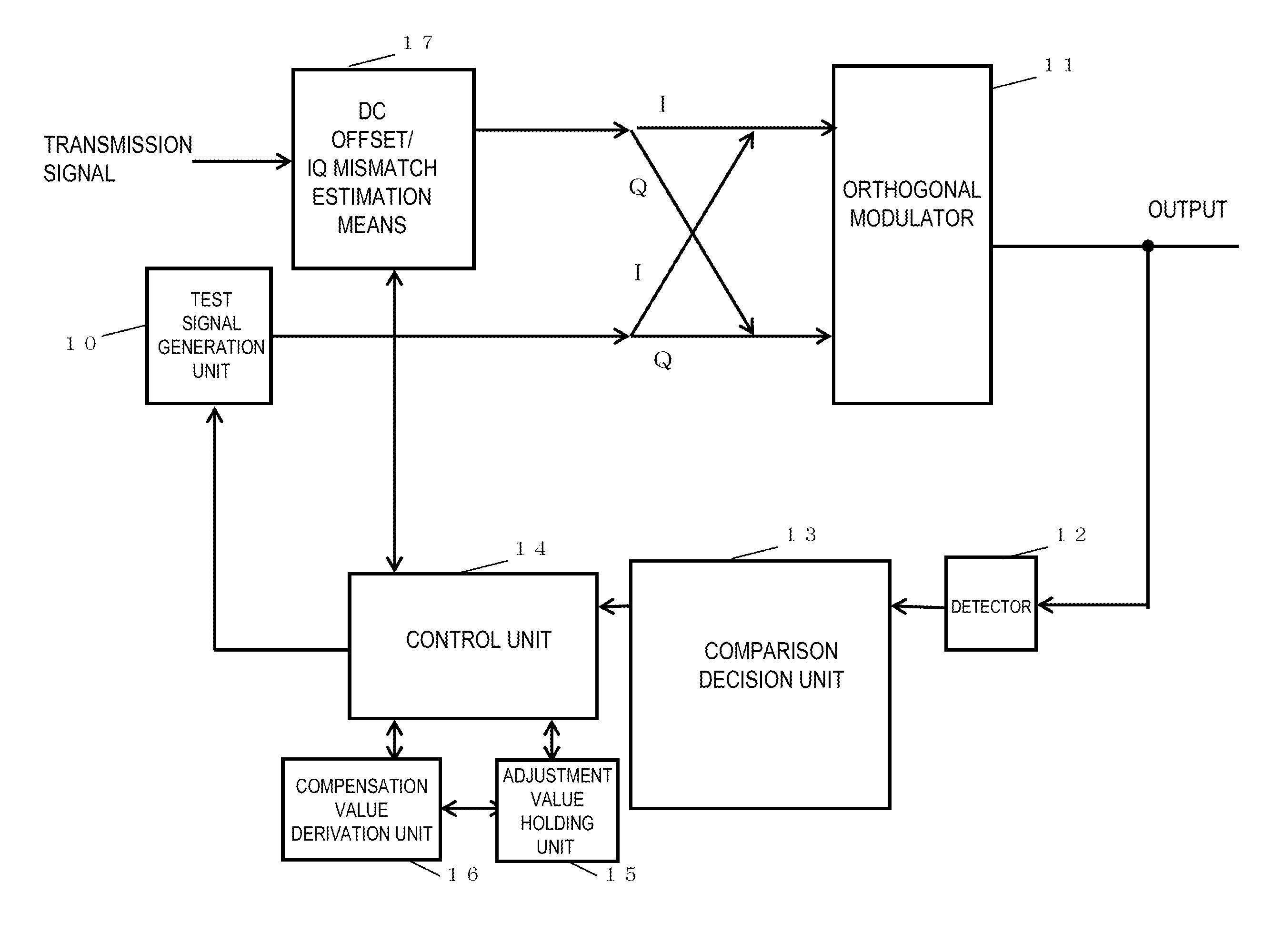
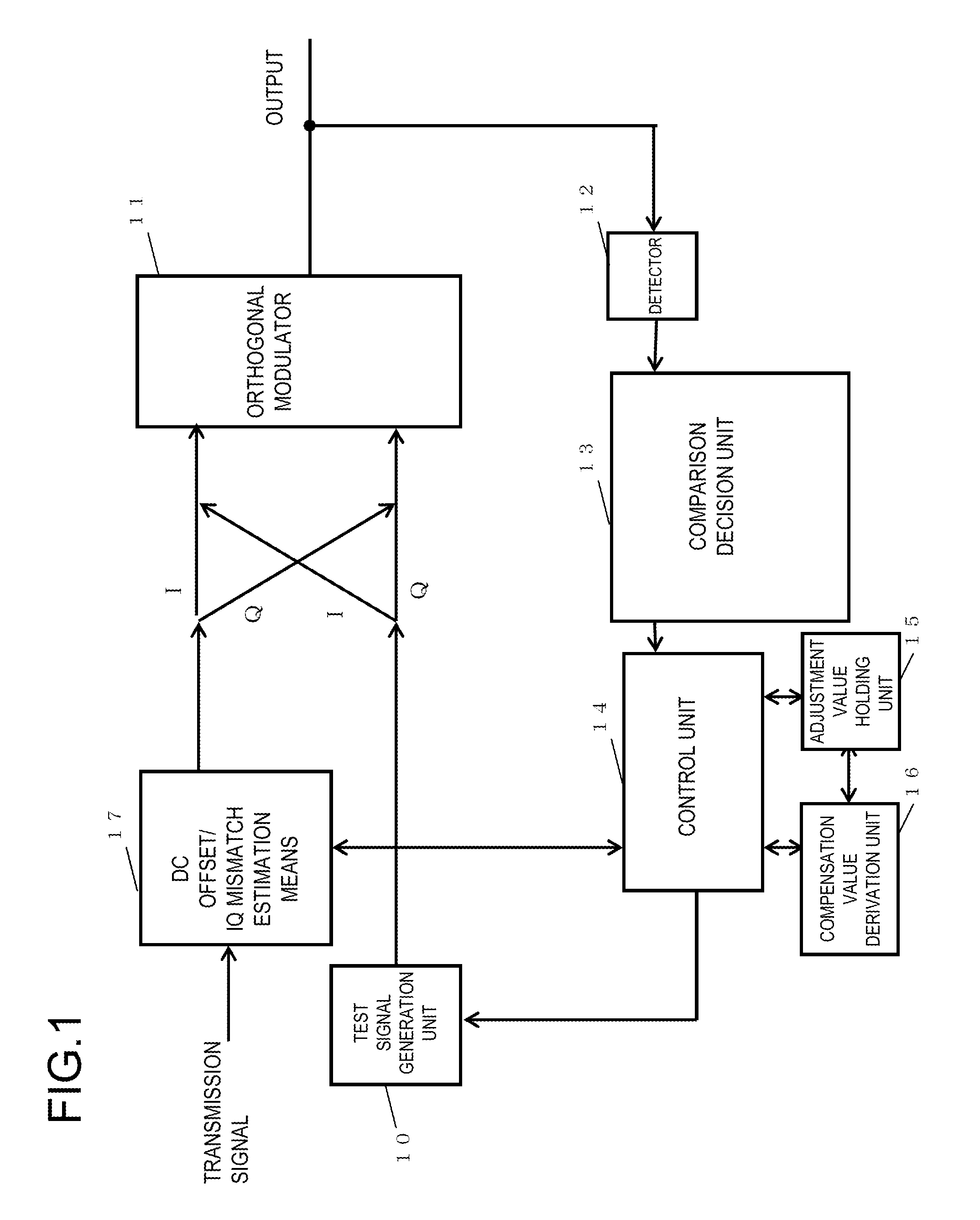
[0108]FIG. 1 is a diagram showing a configuration of a signal processing apparatus according to a first exemplary embodiment of the present invention. Referring to FIG. 1, the signal processing apparatus according to an exemplary embodiment of the present invention includes a test signal generation unit 10, a DC offset / IQ mismatch estimation means 17, an orthogonal modulator 11, a detector 12, a comparison-decision unit 13, a control unit 14, an adjustment value holding unit, and a compensation value derivation unit 16. Each of the units described above generally performs the following processing and operation.

[0109]The test signal generation unit 10 generates a first test signal (I1, Q1) (in which I of (I, Q) indicates an in-phase component signal, while Q of (I, Q) indicates a quadrature component signal) and a second test signal (I2, Q2) that is in a predetermined relationship with the first test signal, and supplies the first and second test signals to the orthogonal modulator 1...

second exemplary embodiment

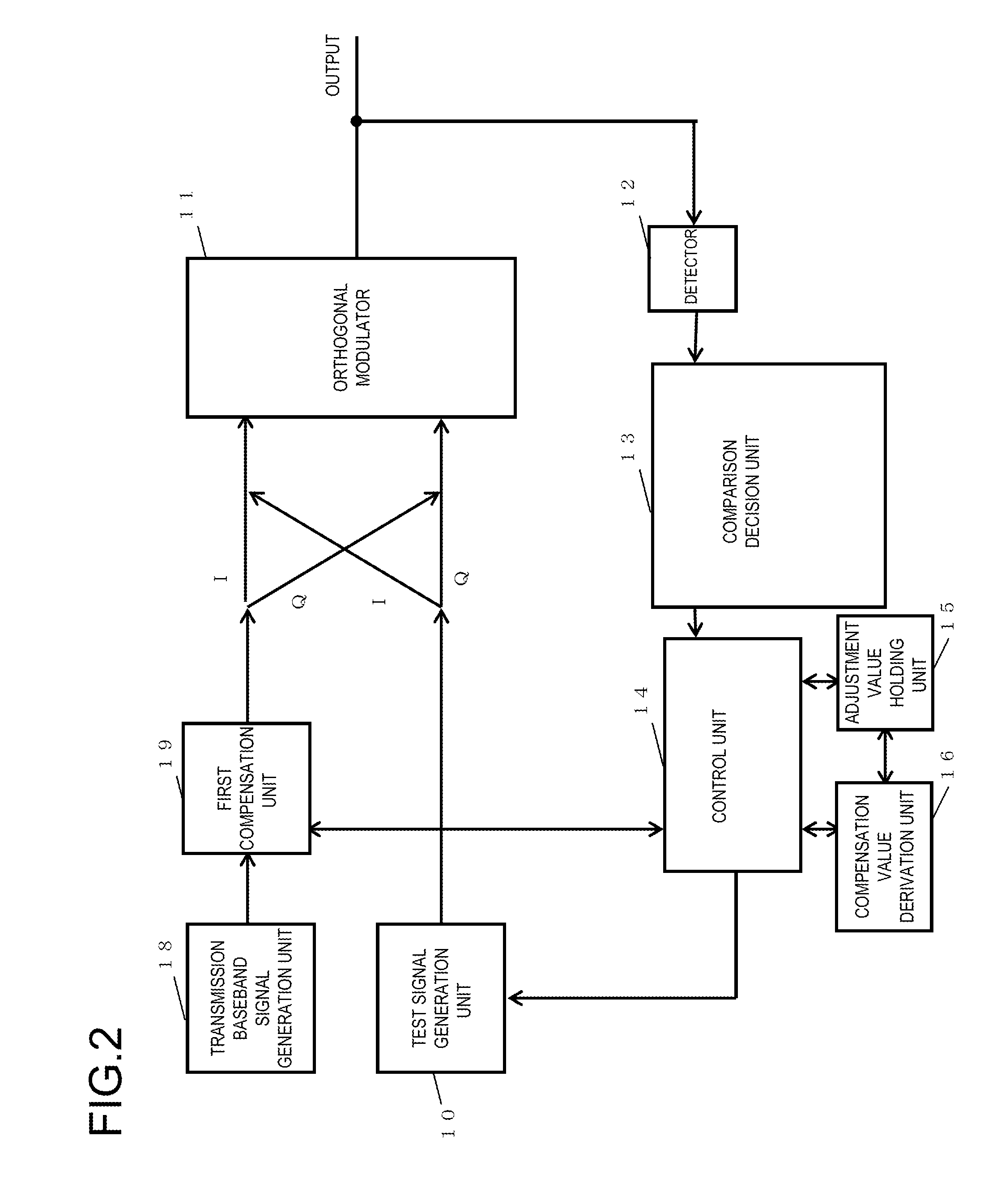
[0115]FIG. 3 is a diagram showing a signal processing apparatus according to a second exemplary embodiment of the present invention. In addition to the configuration of the signal processing apparatus in FIG. 1, this exemplary embodiment further includes a transmission baseband signal generation unit 18 that generates an I-channel signal component and a Q-channel signal component from a transmission signal, and a first compensation unit 19 that receives and compensates for a transmission baseband signal, and supplies the compensated signal to the orthogonal modulator 11, as the first compensation unit 19 form as the means 17 for estimating a DC offset and an IQ mismatch. A test signal generated by the test signal generation unit 10 is indirectly supplied to the orthogonal modulator 11 through the first compensation unit 19. This exemplary embodiment further includes a first switch means 30 that selects one of the transmission baseband signal and the test signal and outputs the selec...

third exemplary embodiment

[0120]FIG. 4 is a diagram showing a signal processing apparatus according to a third exemplary embodiment of the present invention. In addition to the configuration of the signal processing apparatus in FIG. 1, this exemplary embodiment further includes a transmission baseband signal generation unit 18 that generates a signal component of an I channel and a signal component of a Q-channel from a transmission signal, and a first compensation unit 19 that receives and compensates for a transmission baseband signal, and supplies the compensated signal to the orthogonal modulator 11, as the means 17 for estimating a DC offset and an IQ mismatch. The signal processing apparatus includes a third DAC 42 and a fourth DAC 43 each of which converts an output of the first compensation unit 19 to an analog signal, a fifth DAC 44 and a sixth DAC 45 each of which converts a test signal generated by the test signal generator 10 to an analog signal, second switch means 31 that selects one of output...


PUM


Abstract

An apparatus includes a test signal generation unit supplying test signals to an orthogonal modulator and a control unit that based on a result of decision by comparison and decision of detection results of a detector detecting envelopes of modulated signals output from the orthogonal modulator responsive to the test signals, derives adjustment values and a compensation value. An estimation means estimates a DC offset and an IQ mismatch of the orthogonal modulator, based on the derived compensation value. The test signals includes a first set including a first test signal (I1, Q1) and a second test signal (I2, Q2) having a predetermined relationship with the first test signal, and a second set of which in-phase and quadrature components have predetermined relationships respectively with in-phase and quadrature components of the first set.

Description

[0001]This application is the National Phase of PCT / JP2008 / 062396, filed Jul. 9, 2008 which is based upon and claims the benefit of the priority of Japanese patent application No. 2007-181019 (filed on Jul. 10, 2007), the disclosure of which is incorporated herein in its entirety by reference.TECHNICAL FIELD[0002]The present invention relates to a frequency conversion apparatus or a communication transmitting unit that involves frequency conversion.BACKGROUND ART[0003]Carrier leakage suppression and prevention of modulation accuracy deterioration are essential items for ensuring communication quality and for regulatory compliance in an orthogonal demodulator and a radio transmitter that use the orthogonal modulator. In recent years, with an increase in the speed of communication, a demanded performance level has got higher. However, due to circuit configuration constraints caused by a direct conversion architecture and a lower voltage of a process, the performance items described at...

Claims


Application Information

Patent Timeline
IPC IPC(8): G06F19/00G01R29/00
CPCH04L27/364H04L25/06
Inventor YANAGISAWA, KIYOSHIMATSUNO, NORIAKI
Owner NEC CORP
Why Eureka
Try Eureka