Refrigeration system

a refrigeration system and high-pressure technology, applied in the field of refrigeration systems, can solve the problems of limited possibility of accumulation of refrigerant on the high-pressure side, lack of refrigerating capacity, and inability to meet the needs of larger-scale distributed systems, etc., to achieve novel valve control, high pressure, and loss of heat transfer performance

Inactive Publication Date: 2010-08-12
STAR REFRIGERATION
View PDF18 Cites 45 Cited by
  • Summary
  • Abstract
  • Description
  • Claims
  • Application Information

AI Technical Summary

Benefits of technology

[0018]The evaporators are preferably equipped with individual expansion devices to regulate the flow of the refrigerant into each evaporator. It is a preferred feature of this invention that these expansion devices can be similar in type to the traditional valves used in conventional refrigerating systems, provided they can withstand the higher pressure encountered when operating with sub-critical carbon dioxide. The control of the expansion valves is based upon refrigerant temperature and pressure, but set to a relatively low value such that some liquid will, from time to time during normal modulation of the valve, pass from the evaporator to the receiver. In this respect, although the design and construction of these valves is similar to the traditional valves used in conventional systems, the control of the valves is novel. According to another preferred aspect of the invention, this novel control provides significant advantage in the event of a malfunction of one of the individual expansion devices on the evaporators because the excess liquid passed through the evaporator will be trapped by the receiver and will not cause damage to any of the compressors in the system.
[0019]A further preferred feature of this invention enables lubricant, which has passed through the oil separator and circulated through the ref...

Problems solved by technology

There is therefore limited possibility for accumulation of refrigerant on the high pressure side, as is required with the use of a conventional expansion valve.
They are not well suited to larger distributed systems where the refrigerating capacity is variable, where there are...

Method used


Image

  • Refrigeration system
  • Refrigeration system

Examples


Embodiment Construction

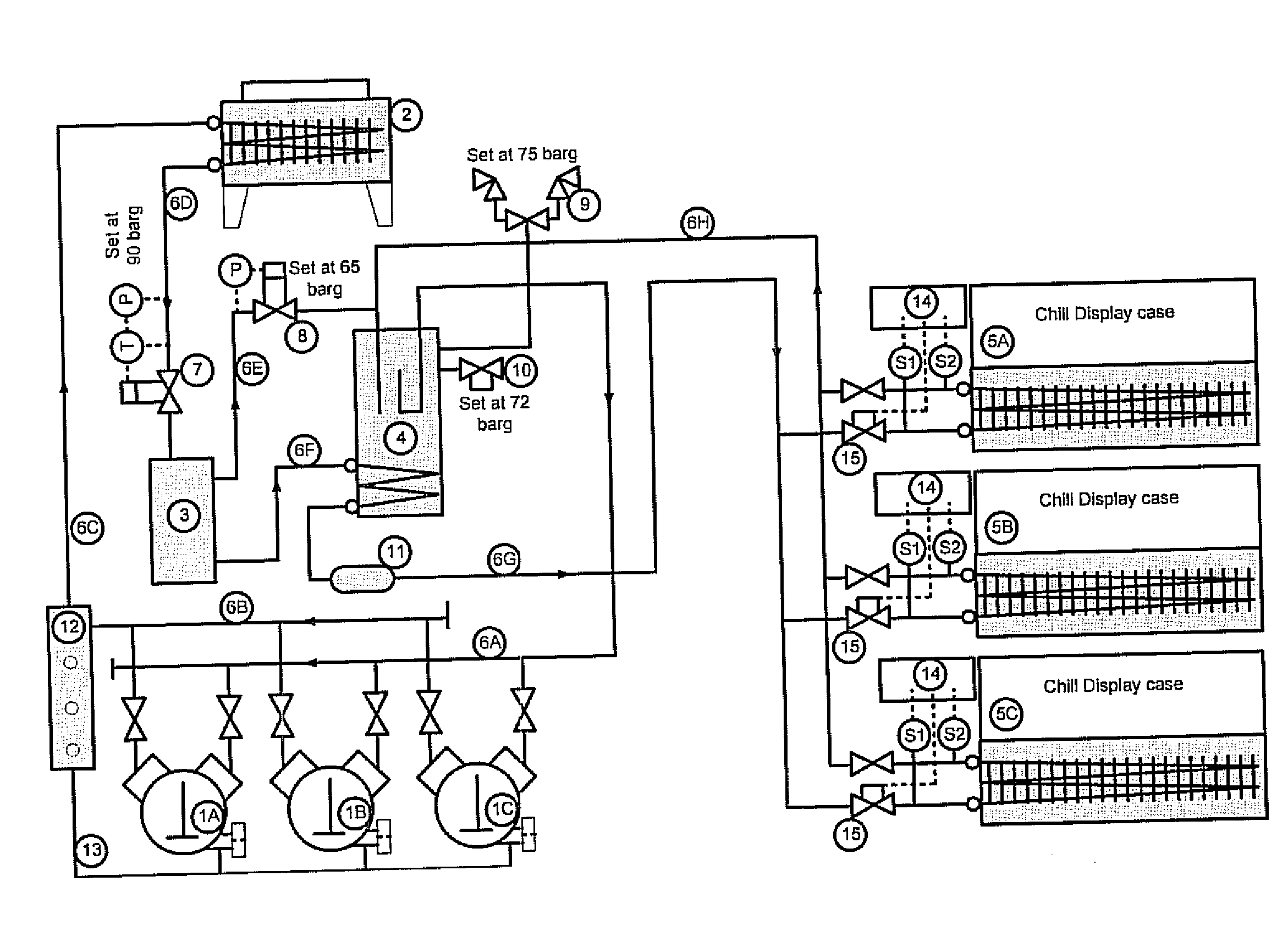
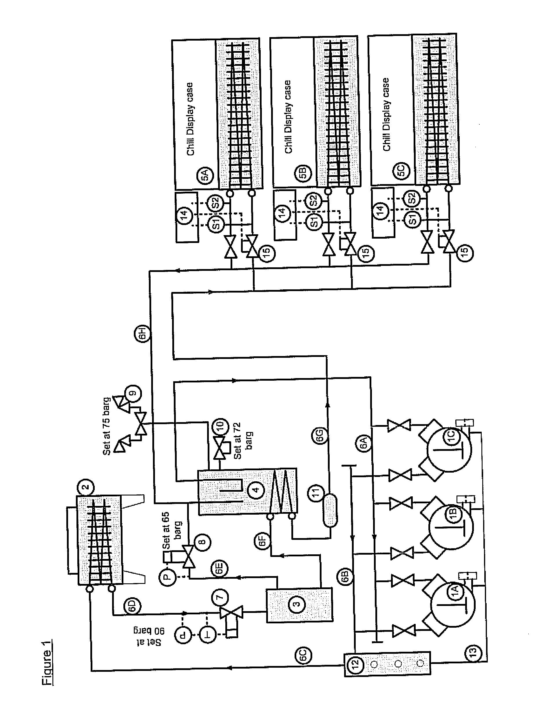
[0025]One embodiment of the invention is illustrated schematically in FIG. 1.

[0026]In this system the refrigerant carbon dioxide is used for cooling of chilled food display cases in a supermarket. A set of one or more compressors (1A, 1B etc) pump refrigerant gas to a high pressure condition at which it can reject heat to atmosphere or some other cooling medium. The gas is conducted from the compressor(s) through pipes (6B, 6C) to a heat rejection device (2). From the heat rejection device the cooled refrigerant passes through pipes (6D, 6F) to a heat exchanger located in the receiver (4) and from there through pipes (6G) to a set of one or more system evaporators (5A, 5B etc).

[0027]When the temperature of the heat sink (the zone to which heat is rejected from heat rejection device (2)) is higher than approximately 25° C. then the compressors will be required to raise the carbon dioxide gas to a supercritical pressure, typically in the range 80 to 120 bar absolute. This can be descr...


PUM


Abstract

A refrigerating system comprises a compressor (1A, 1B, 1C), a heat rejection device (2), an expansion device (15), an evaporator (5A, 5B, 5C) and a receiver (4), capable of operating with the compressor discharge higher than the critical pressure of the refrigerant; where
    • the flow outlet from the heat rejection device is regulated by a pressure control valve (7),
    • the pressure downstream of the pressure control valve is regulated by a gas vent valve (8),
    • the refrigerant flow to the evaporator is further regulated by an automatic control device (41, 52, 14) at the inlet to the evaporator, and
    • the automatic control device being set to permit intermittent flow of liquid refrigerant to the receiver during normal operation of the system.
The refrigerant may be carbon dioxide, which may operate under transcritical pressures e.g. 80 to 120 bar absolute. The receiver acts as a trap for any liquid from the evaporator and ensures that the gas flow to the compressor suction is dry.

Description

CROSS-REFERENCE TO RELATED APPLICATION[0001]This application claims priority of United Kingdom Patent Application 0902192.4 filed Feb. 11, 2009.TECHNICAL FIELD[0002]The present invention relates to a refrigeration system, especially utilising carbon dioxide as refrigerant.BACKGROUND[0003]The prohibition of chlorofluorocarbons as refrigerants, which results from their deleterious effect on the ozone layer, has led to a number of alternative strategies to provide cooling without adverse environmental impact. The majority of systems have used hydrofluorocarbons, which have no effect on stratospheric ozone, but which in many cases have a high global warming potential and are therefore known to contribute to climate change through global warming. Carbon dioxide is a suitable fluid for use as a refrigerant, and was one of the earliest fluids used when mechanical refrigeration was developed in the raid 19th century. Carbon dioxide has no effect on the ozone layer, and is present in the atm...

Claims


Application Information

Patent Timeline
IPC IPC(8): F25D17/02F25B1/00F25B43/00
CPCF25B5/02F25B9/008F25B43/006F25B49/005F25B2309/061F25B2341/063F25B2600/2525F25B2400/075F25B2400/13F25B2400/22F25B2400/23F25B2600/2501F25B2600/2513F25B2400/051F25B41/20
Inventor PEARSON, ANDREW BRASH
Owner STAR REFRIGERATION
Why Eureka
Try Eureka