Gas-liquid separator and air conditioner equipped with the same

Inactive Publication Date: 2010-08-12
MITSUBISHI ELECTRIC CORP
View PDF3 Cites 9 Cited by
  • Summary
  • Abstract
  • Description
  • Claims
  • Application Information

AI Technical Summary

Benefits of technology

[0009]According to the present invention, by providing an expanded end section having a width greater than the diameter of that portion of the inlet pipe which crosses the vessel of the gas-l

Problems solved by technology

When the refrigerant flows into the evaporator in the gas-liquid two phase state, the pressure loss of the refrigerant

Method used


Image

  • Gas-liquid separator and air conditioner equipped with the same
  • Gas-liquid separator and air conditioner equipped with the same
  • Gas-liquid separator and air conditioner equipped with the same

Examples


embodiment 1

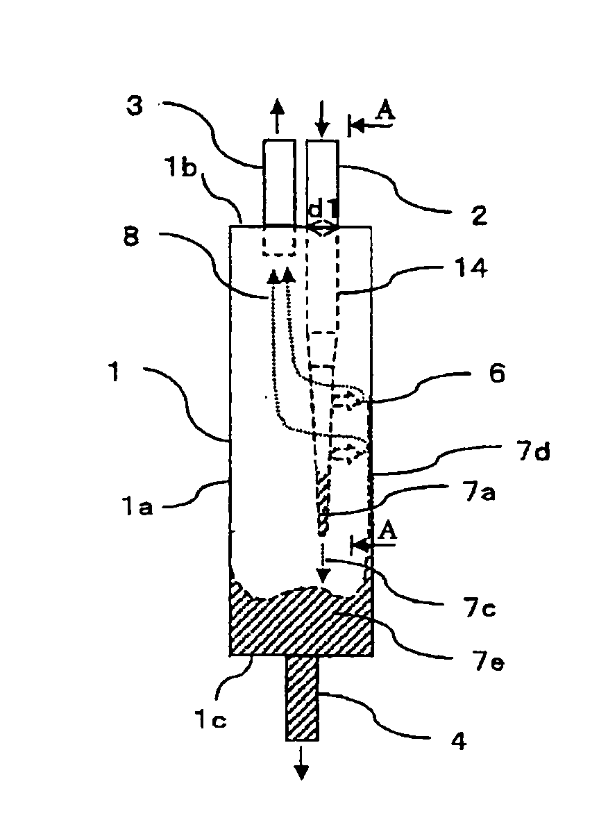
[0038]FIG. 1 is a front view showing a gas-liquid separator according to embodiment 1 of the present invention. The gas-liquid separator comprises a vessel 1 including a cylindrical side wall 1a, a top wall 1b and a bottom wall 1c, an inlet pipe 2 mounted to and penetrated through the top wall 1b, and an upper outlet pipe 3 mounted to the top wall 1b in parallel to the inlet pipe 2, and a lower outlet pipe 4 mounted to the bottom wall 1c of the vessel 1. The vessel 1 is for achieving gas-liquid separation of a gas-liquid mixture fluid.

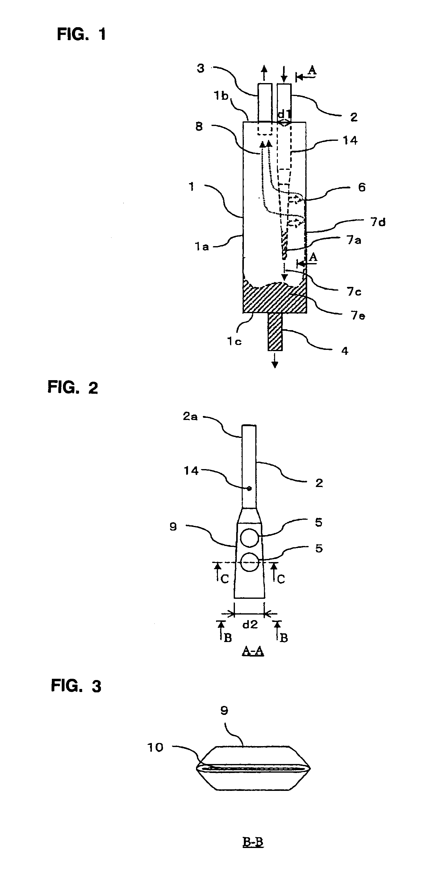
[0039]FIG. 2 is a side view showing only the inlet pipe 2 as seen along the line A-A of FIG. 1. The inlet pipe 2 is connected at one end to an external circuit and at the other end comprises a connecting pipe 2a of a circular cross-section hermetically penetrating through the top wall 1b of the vessel 1 and an expanded end portion 9 connected to the other end of the connecting pipe 2a and having a cross-section of a flat elongated shape as shown in FIG...

embodiment 2

[0073]Also, as shown in FIG. 12, the inlet pipe 2 may be expanded at the lower portion into a cylindrical configuration to provide an expanded end portion 12 and the lateral holes 5 are provided in the side face of the expanded end portion 12. In this example, the bottom plate 11 with the lower hole 10 is brazed at the lower portion of the expanded end portion 12. For example, the diameter d1 of the connecting pipe 2a is about 6 mm, the diameter of the expanded end portion 12 is about 13 mm, the width d2 of the expanded end portion 12 being about two times larger than the diameter d1 of the connecting pipe 2a. The diameter of the lateral holes 5 is about 6 mm and the diameter of the lower hole 10 is about 2 mm.

[0074]According to this arrangement, the width (diameter) d3 of the expanded end portion 12 is larger than the diameter d1 of the inlet pipe at the portion intersecting with the vessel of the gas-liquid separator, so that, as shown in FIG. 13, the thickness of the liquid film ...

embodiment 3

[0086]In the example illustrated in FIG. 15, the lower portion of the inlet pipe 2 is expanded into a rectangular parallelepiped configuration to provide an expanded end portion 13 having a cross section of a rectangular or square shape and the lateral holes 5 may be provided on the side face of the expanded end portion 13. In this example, the expanded end portion 13 has brazed at its lower end the bottom plate 11 with the lower hole 10.

[0087]According to this arrangement, the expanded end portion 13 has the width d4 of larger than the diameter d1 of the inlet pipe at the portion intersecting with the vessel 1 of the gas-liquid separator and has corners, so that, as shown in FIG. 16, at the square cross section of the expanded end portion 13, the liquid film of the refrigerant liquid 7a flowing in the vicinity of the corners is thick and the liquid film of the refrigerant liquid 7b flowing at the center of the sides is thin. Therefore, the amount of refrigerant liquid 7b discharged...


PUM

PropertyMeasurementUnit
Speedaaaaaaaaaa
Flow rateaaaaaaaaaa
Diameteraaaaaaaaaa

Abstract

To improve the separation efficiency of a gas-liquid separator in the gas-liquid separator and an air conditioner, the gas-liquid separator having a vessel with an inlet pipe and an outlet pipe is arranged such that an exit end section of the inlet pipe is formed to be closed or to have a gap, an expanded end section having a width greater than the diameter of that portion of the inlet pipe which crosses a container of the gas-liquid separator is provided, and that a lateral hole is formed in a side face of the expanded end section. Refrigerant vapor and refrigerant liquid are efficiently separated from each other at the expanded end section, and this improves separation efficiency of the gas-liquid separator.

Description

TECHNICAL FIELD[0001]This invention relates to a gas-liquid separator and an air conditioner equipped with the same.BACKGROUND ART[0002]In a refrigerant cycle, a refrigerant liquid condensed in the condenser is depressurized by an expansion valve to become a gas-liquid two-phase state fluid in which the refrigerant vapor and the refrigerant liquid is mixed and flows into an evaporator. When the refrigerant flows into the evaporator in the gas-liquid two phase state, the pressure loss of the refrigerant when passing through the evaporator is large, resulting in the decrease in the energy efficiency of the air conditioner.[0003]Therefore, the energy efficiency of the air conditioner can be improved by separating the refrigerant into the refrigerant vapor and the refrigerant liquid through the use of a gas-liquid separator before the refrigerant flows into the evaporator so that only the refrigerant liquid flows through the evaporator to decrease the pressure loss generated when the re...

Claims


Application Information

Patent Timeline
IPC IPC(8): F25B43/00
CPCF25B43/00F25B43/02F25B2400/23F25B2400/02
Inventor MURAKAMI, HIROKINAGAI, HIRONORISAITO, TADASHIMAKINO, HIROAKIHAYAMARU, YASUHIDEYAMAMOTO, KAZUHIDE
Owner MITSUBISHI ELECTRIC CORP
Why Eureka
Try Eureka