Apparatus and method for reducing gaseous inclusions in a glass

a technology of glass and gaseous inclusions, which is applied in the field of glass manufacturing system and a method for reducing gaseous inclusions in glass, can solve the problems of limiting the ability of fining and oxygen re-absorption, affecting the quality of glass, and expensive processing of glass was

Inactive Publication Date: 2010-08-12
CORNING INC
View PDF37 Cites 36 Cited by
  • Summary
  • Abstract
  • Description
  • Claims
  • Application Information

AI Technical Summary

Benefits of technology

[0008]In yet another aspect of the present invention there is provided a glass manufacturing system including: (a) a melting vessel that melts batch materials and forms molten glass at a melting temperature TM, where the molten glass comprises a multivalent oxide material; (b) a refractory tube, coupled to the melting vessel, that receives the molten glass and cools the molten glass to a cooling temperature TC which is less than TM, where the molten glass remains within the refractory tube for a predetermined resident time to reduce a volume of the gaseous inclusions in the molten glass and cause gas species to migrate out of the gaseous inclusions into the molten glass such that at least a portion of the gaseous inclusions collapse into the molten glass; and (c) a fining vessel, coupled to the refractory tube, that heats the cooled molten glass to a fining temperature TF≧TM.

Problems solved by technology

Arsenic-containing compounds are generally toxic, and processing of glass with arsenic results not only in manufacturing wastes that are expensive to process, but also creates disposal issues relative to the display device itself after the useful life of the device.
Unfortunately, many alternative fining agents typically release less oxygen, and / or at too low a temperature, and reabsorb too little O2 during the conditioning process relative to established fining agents such as arsenic, thereby limiting their fining and oxygen re-absorption capabilities.
Thus, during the fining stage of the glass production process (i.e. while the glass is within the fining vessel), the fining agent may produce an insufficient quantity of oxygen to effectively fine the glass within the fining vessel.

Method used


Image

  • Apparatus and method for reducing gaseous inclusions in a glass
  • Apparatus and method for reducing gaseous inclusions in a glass
  • Apparatus and method for reducing gaseous inclusions in a glass

Examples


Embodiment Construction

[0019]In the following description, a brief discussion about a typical glass making process is provided first and then a detailed discussion is provided to describe details and enable a thorough understanding about several exemplary embodiments of the glass manufacturing system and method used to reduce gaseous inclusions in a glass in accordance with the present invention. However, it will be apparent to one having ordinary skill in the art, having had the benefit of the present disclosure, that the present invention may be practiced in other embodiments that depart from the specific details disclosed herein. Moreover, it will be apparent to one having ordinary skill in the art that descriptions of well-known devices, methods and materials have been omitted so as not to obscure the description of the present invention.

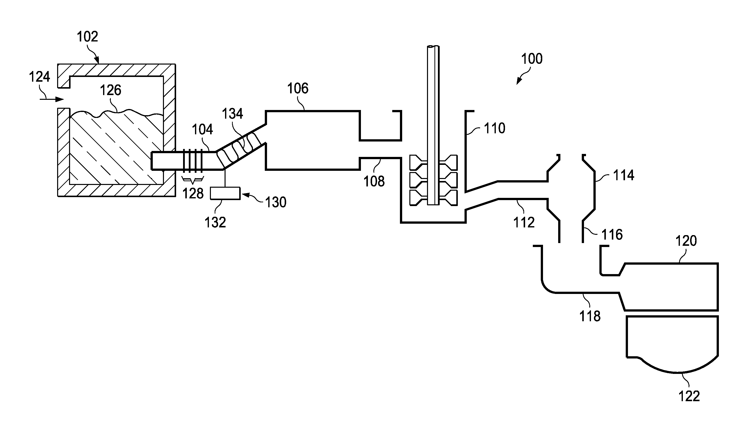
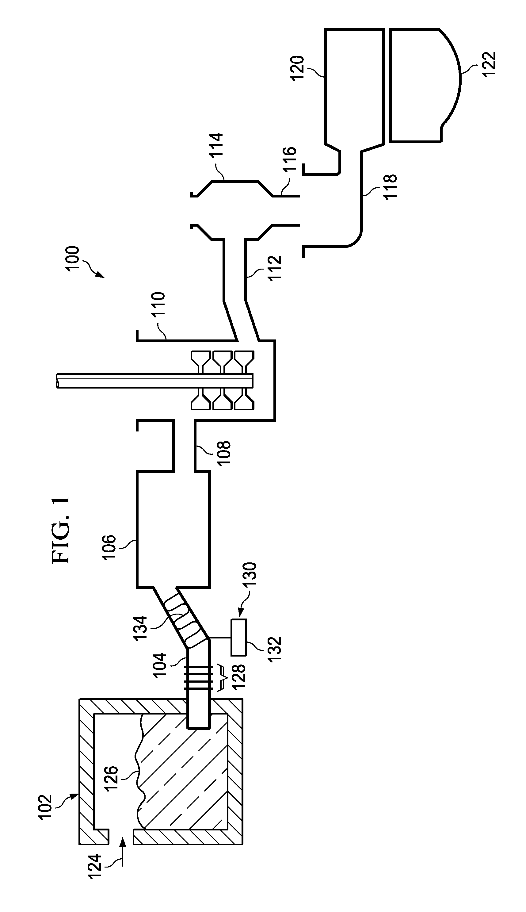
[0020]In a typical glass making process raw feed materials are heated in a furnace (melter, melting vessel) to form a viscous mass (glass melt). Furnaces are generall...


PUM

PropertyMeasurementUnit
TCaaaaaaaaaa
TMaaaaaaaaaa
TMaaaaaaaaaa

Abstract

A glass manufacturing system and a method are described herein for reducing gaseous inclusions in high melting temperature or high strain point glasses, such as those that are used as glass substrates in flat panel display devices. In one embodiment, the method including the steps of: (a) heating a batch material within a melting vessel to form molten glass at a melting temperature TM, the molten glass comprising a multivalent oxide material; (b) heating the molten glass within a fining vessel to a fining temperature TF≧TM; and (c) cooling the molten glass within a refractory tube after the first heating step or after the second heating step to a cooling temperature TC less than TM, where the molten glass remains within the refractory tube for a predetermined resident time to reduce a volume of the gaseous inclusions in the molten glass and cause gas species to migrate out of the gaseous inclusions into the molten glass such that at least a portion of the gaseous inclusions collapse into the molten glass.

Description

CROSS-REFERENCE TO RELATED APPLICATION[0001]This application is a Continuation-in-Part and claims the benefit of priority under 35 U.S.C. §120 to U.S. patent application Ser. No. 12 / 269,310, filed on Nov. 12, 2008, the content of which is relied upon and incorporated herein by reference in its entirety.TECHNICAL FIELD[0002]The present invention relates to a glass manufacturing system and a method for reducing gaseous inclusions in a glass. In one embodiment, the glass manufacturing system and method are particularly useful for reducing gaseous inclusions in high melting temperature or high strain point glasses, such as those that are used as glass substrates in flat panel display devices.BACKGROUND[0003]Flat display devices such as liquid crystal displays (LCDs) are made from flat glass substrates or sheets. Conventional glass manufacturing processes for LCD glass typically begin by melting glass precursors—feed materials—in a melting furnace. Reactions which occur during this melti...

Claims


Application Information

Patent Timeline
Patent Type & Authority Applications(United States)
IPC IPC(8): C03B5/16C03B27/00
CPCC03B5/225C03B7/07C03B5/23C03B5/16C03B5/235
Inventor ANTOINE, KEISHA CHANTELLE ANNDELAMIELLEURE, MEGAN AURORAPETERSON, IRENE MONA
Owner CORNING INC
Why Eureka
Try Eureka