Beveled block pallet

a beveled block and pallet technology, applied in the field of beveled block pallets, can solve the problems of affecting the lead board of the pallet with significant force, affecting the work efficiency of the pallet, and affecting the shear capacity of the pallet, so as to reduce the weight of the pallet and improve the shear capacity

Inactive Publication Date: 2010-08-12
MILLER DOWEL
View PDF78 Cites 15 Cited by
  • Summary
  • Abstract
  • Description
  • Claims
  • Application Information

AI Technical Summary

Benefits of technology

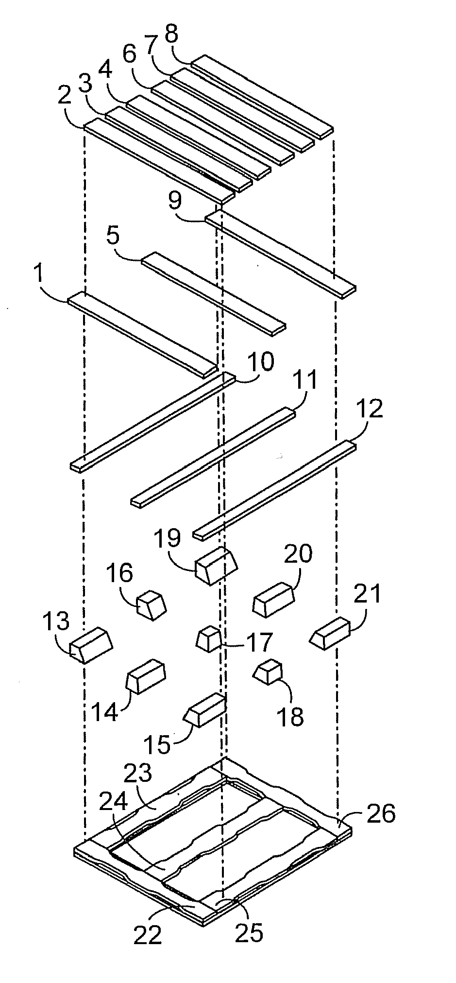
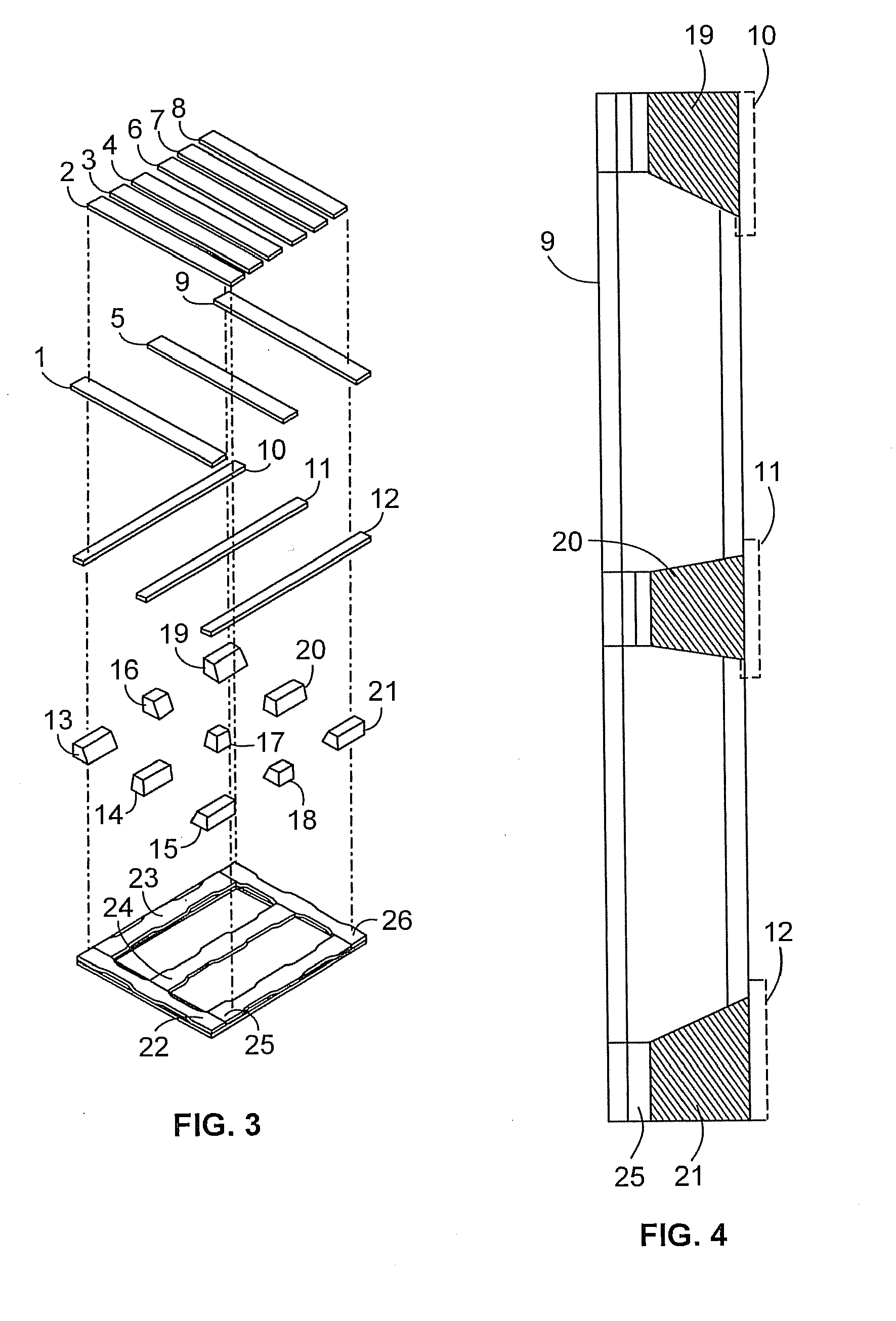
[0009]The use of beveled blocks in the manufacturing of stringer pallets allows for designing for maximum strength of the blocks with regard to shear resistance while reducing the weight of the pallet due to the block size reductions. The beveled block also allows for narrow top stringers and wider bottom boards. The wider bottom face of the block provides for improved shear capacity between the bottom stringers and the blocks and the bottom lead boards and the blocks. It also allows the placement of additional wood dowels while maintaining proper spacing of the dowels between each other, between edges both loaded and unloaded and vertically through the block.

Problems solved by technology

In many pallets, damage can occur at their lead boards.
As a fork lift or other mechanism is brought to engage a pallet, it will often impact the lead board of the pallet with significant force.
This impact force may disengage the lead board or otherwise damage it, yielding a worn or damaged pallet that may not work as well and may be dangerous to users and merchandise.
Also, as pallets are used, they can become worn and weakened, causing some of the stringers or deck boards to break or become at least partially detached, rendering the pallet inoperable or in a dangerous condition.
The use of nails or other metal fastener devices can also render pallets dangerous.
Many times, the damage to a pallet occurs where the metal nail goes into the wood.
The use of metal fasteners can cause splitting in the stringers, lead boards or deck boards.
Further faults of the typical metal fastener approach include product damage or personal injury caused by exposed fasteners and inadequate joint stiffeners.
Also, when a nailed pallet is loaded and moved in service the nails tend to pop up or withdraw partially leaving exposed nail heads called “nail pops” which damage product.
When the wood dries out it often cleaves or further splits at nail locations.
Since the wood piece has no other method to hold it to the adjacent wood element it falls off the pallet causing the pallet to degrade and become unacceptable.
Further, in nailed pallets the connections become loose and sloppy due to how the nails work in the nail track and oval out the nail trace along the grain lines.
These sloppy connections lead to permanent deformation in the pallet such that they do not lay flat on the floor and stack horizontally in the pallet racks.
In addition the pallet loses its stiffness due to these factors which means that under load the pallet deforms excessively (creeps in bending) and this potentially leads to failure from the pallets slipping out of the racks, a dangerous situation.
The creep deflection also damages product that is supported by the pallet.
However, many of these methods require costly machinery or a great deal of time and effort and put workers at significant safety risk.
Nails and other metallic fasteners can be a great hindrance in efforts to disassemble pallets.
Further, if the pallets are chipped the metallic fasteners increase the cost of processing the chips as the fasteners (or parts of fasteners) have to be removed from the chips or sawdust.
The presence of, for example, nails, prevents the use of standard saws or similar devices, which do not effectively cut through nails.
First, they are often large, unwieldy and expensive.
Second, oftentimes the nails remain in the stringers or deck boards after disassembly.
In order to reuse the boards in optimal condition, the nails need be removed, requiring additional time with attendant increased cost and expense.
However, there have been problems implementing RFID systems.
One problem that faces RFID technology is that metal can prevent RFID readers from operating properly.
Further, liquid inside of objects can absorb RF signals, making reading more difficult.
However, nails and other metallic fasteners often cannot be used to construct a pallet with dry wood because they will cause checking and damage to the wood during construction.
Another problem that exists with the current metal fastener green wood pallets in the marketplace is that the blocks within a pallet are often found to split due to the use of solid sawn blocks that are green.
However, there are numerous disadvantages to such a pallet.
A second disadvantage to such a pallet is the required use of external clamps or similar devices to hold the pieces together in position while the glue sets.
A third disadvantage of this technique is the excessive amount of time between initial alignment and ultimate formation of the pallet.
This waste of time stems from the requirement of waiting for the glue to set before use of the pallet.
In a metal fastener type pallet the components will fall off the pallet when the failure separates the piece from any one metal fastener.

Method used


Image

  • Beveled block pallet
  • Beveled block pallet
  • Beveled block pallet

Examples


Embodiment Construction

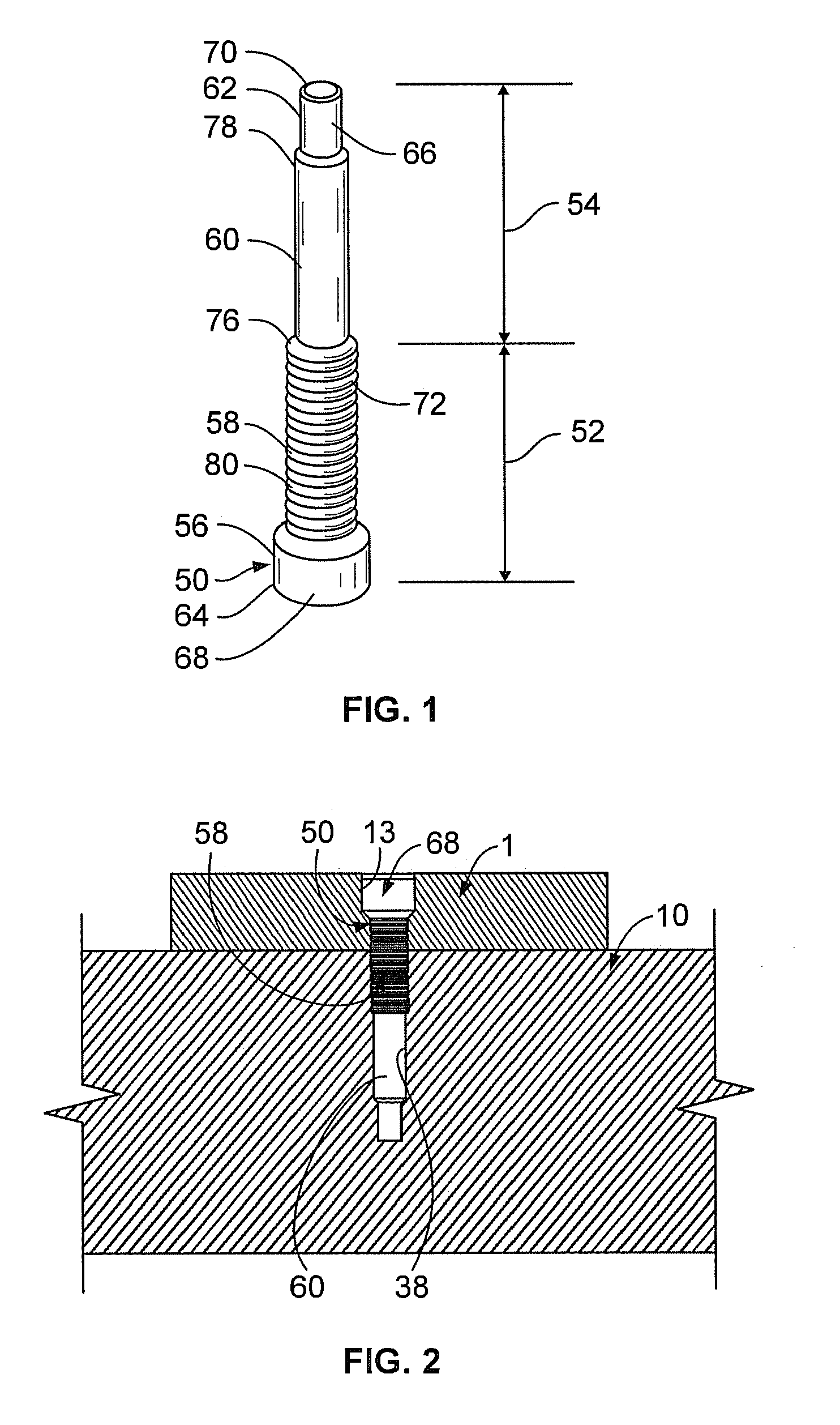
[0032]Referring to FIG. 1, one embodiment of a wooden dowel 50 can be seen. The dowel 50 comprises a first portion 52 and a second portion 54. The dowel may have a plurality of dowel sections, a first section 56, middle sections 58, 60, and last section 62. While in a preferred embodiment, the dowel 50 has two middle sections 58, 60 other embodiments may have no middle section, one middle section, or three or more middle sections. The first and last sections 56, 62 may have side walls 64, 66 and end walls 68, 70, respectively. Each of the middle sections 58, 60 may have side walls 72, 74 and step walls 76, 78, respectively. In a preferred embodiment, each of the sections 56, 58, 60, 62 are contiguous to another section 56, 58, 60, 62. The sidewalls 64, 66, 72, 74 define a cross-sectional size for their respective sections 56, 58, 60, 62. In a preferred embodiment, the cross-sectional size of the sidewalls 64, 66, 72, 74 decreases as one progresses from the first section 56 to the la...


PUM


Abstract

A beveled block pallet is disclosed, the pallet being stringers supporting blocks, the blocks supporting stringers. The blocks are tapered to form a trapezoid shape to permit more strength with less weight.

Description

FIELD OF INVENTIONBackground of the Invention[0001]Pallets of various types are known in the art for use in shipping and warehousing of material. Typical pallets are constructed of wood and include parallel stringers to which transverse deck boards are then nailed or otherwise secured with metal fastener devices to form the pallet. Pallets need to have sufficient strength to withstand the weight of objects loaded thereon and other impact forces to which the pallets are subjected when objects are loaded onto them and when the pallets are moved, as by a fork-lift truck or the like. In addition pallets must carry loads when placed in storage racks where they are only supported at their ends in either direction.[0002]In many pallets, damage can occur at their lead boards. As a fork lift or other mechanism is brought to engage a pallet, it will often impact the lead board of the pallet with significant force. This impact force may disengage the lead board or otherwise damage it, yielding...

Claims


Application Information

Patent Timeline
Patent Type & Authority Applications(United States)
IPC IPC(8): B65D19/31B65D19/38
CPCB65D19/0091B65D2519/00029B65D2519/00064B65D2519/00099B65D2519/00572B65D2519/00293B65D2519/00323B65D2519/00348B65D2519/00378B65D2519/00273B65D2203/10
Inventor MILLER, MICHAELTINGLEY, DANIELHAEBLER, PHILLIP
Owner MILLER DOWEL
Why Eureka
Try Eureka