
Production facility and production process for hot dip galvannealed steel plate

a production facility and production process technology, applied in the direction of heat treatment equipment, lighting and heating equipment, furniture, etc., can solve the problems of limiting production schedules, difficult to substantially maintain the optimum production conditions, and difficult to start cooling at the optimum

Active Publication Date: 2010-08-12
NIPPON STEEL CORP
View PDF2 Cites 15 Cited by
  • Summary
  • Abstract
  • Description
  • Claims
  • Application Information

AI Technical Summary

Benefits of technology

The patent text describes a problem in the production process of hot dip galvannealed steel plates, where the optimal soaking and cooling conditions constantly fluctuate due to production specifications and external factors such as plating deposition, steel type, plating bath composition, and line speed. The conventional fixed type soaking and cooling zones in the production facility cannot maintain optimal conditions, leading to poor quality and slow production schedules. The patent aims to provide a production facility and process that can easily adjust the soaking and cooling zones to optimal conditions in real-time, regardless of changes in the plating deposition, steel type, plating bath composition, and line speed.

Problems solved by technology

However, in an actual production process, the optimum soaking temperature and soaking time constantly fluctuate due to the production specifications and other external factors, so in a conventional known alloying facility provided with a fixed type soaking zone and fixed type cooling zone using the production conditions described in Japanese Patent No. 3,400,289, it is difficult to start the cooling at the optimum point where the alloying reaction should be ended and it is difficult to substantially maintain the optimum production conditions.
On the other hand, in the case of an alloying facility provided with a movable type soaking zone and a movable type cooling zone described in Japanese Patent No. 2,848,074, it is possible to make the soaking zone and cooling zone move in accordance with the fluctuating optimum production conditions, but time is required for switching a soaking furnace and cooling furnace, so this greatly restricts production schedules and therefore operation is difficult.
Regarding the response when switching between soaking and cooling, time is required in the same way as Japanese Patent No. 2,848,074 and the operation is believed difficult.
Further, Japanese Patent Publication (A) No. 63-121644 discloses a furnace in which the soaking by a heating gas and the cooling by a cooling gas are performed in the same region, but for example when performing soaking by a heating gas, then cooling by a cooling gas, since there are no means for exhausting the heating gas, the heating gas and the cooling gas are mixed in the region and sufficient cooling becomes difficult.
It is believed that time would be required for response when switching between soaking and cooling and that operation would be difficult.

Method used


Image

  • Production facility and production process for hot dip galvannealed steel plate
  • Production facility and production process for hot dip galvannealed steel plate
  • Production facility and production process for hot dip galvannealed steel plate

Examples


examples

[0073]Examples of the present invention will be explained in comparison with comparative examples.

example i

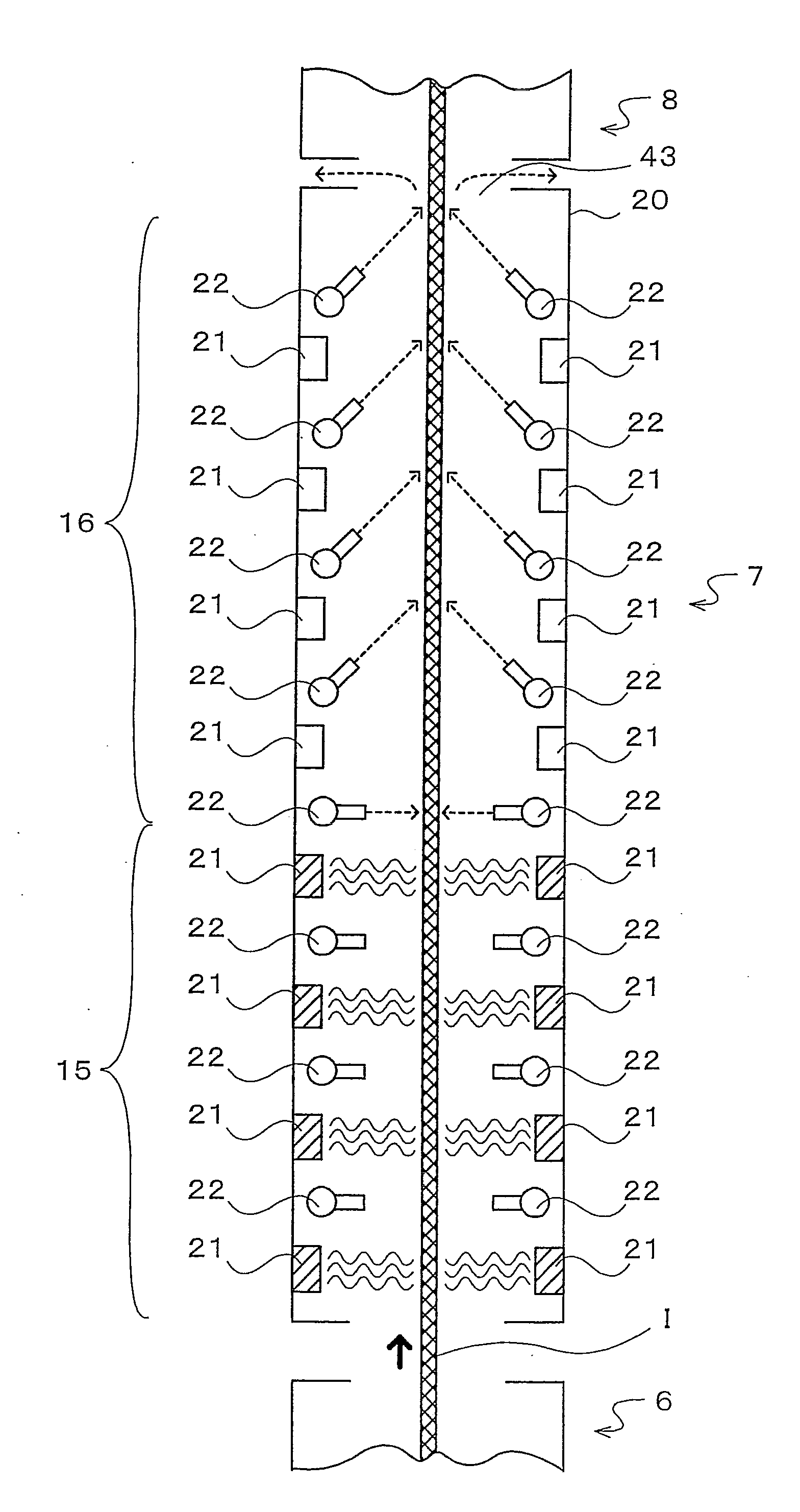
[0074]First, the case of using a soaking / cooling furnace for soaking, then cooling steel plate will be explained. The results of using the production facility of the present invention and the conventional type production facility to produce hot dip galvannealed steel plate from the test materials of the steel types of the compositions shown in Table 1 under various types of production conditions are shown in Table 2. Note that the length in the line direction of the soaking / cooling furnace having the production facility of the present invention was made 25 m. For the conventional type production facility, the length in the line direction of the fixed type soaking furnace was made 14.2 m, and the line in the line direction of the fixed type cooling furnace was made 10.8 m. Further, the Al concentration in the plating bath was made 0.134 mass % at both the production facility and conventional type production facility of the present invention.

TABLE 1CSiMnPSTest Material 10.0020.0240.16...

example ii

[0082]Next, the case of using a soaking / cooling furnace for cooling, then soaking steel plate will be explained. The results of using the production facility of the present invention and a conventional type production facility to produce hot dip galvannealed steel plate from the test materials of the steel types of the compositions shown in Table 3 under various types of production conditions are shown in Table 4. Note that the length in the line direction of the soaking furnace of the production facility of the present invention was made 25 m. The conventional type production facility had a length in the line direction of the fixed type soaking furnace of 14.2 m and a length in the line direction of the fixed type cooling furnace of 10.8 m. Further, the Al concentration in the plating bath was made 0.134 mass % in both of the production facility of the present invention and the conventional type production facility.

TABLE 3CSiMnPSTest Material 30.0020.0030.80.0350.013* Compositions ...


PUM

PropertyMeasurementUnit
peak temperatureaaaaaaaaaa
temperatureaaaaaaaaaa
peak temperatureaaaaaaaaaa

Abstract

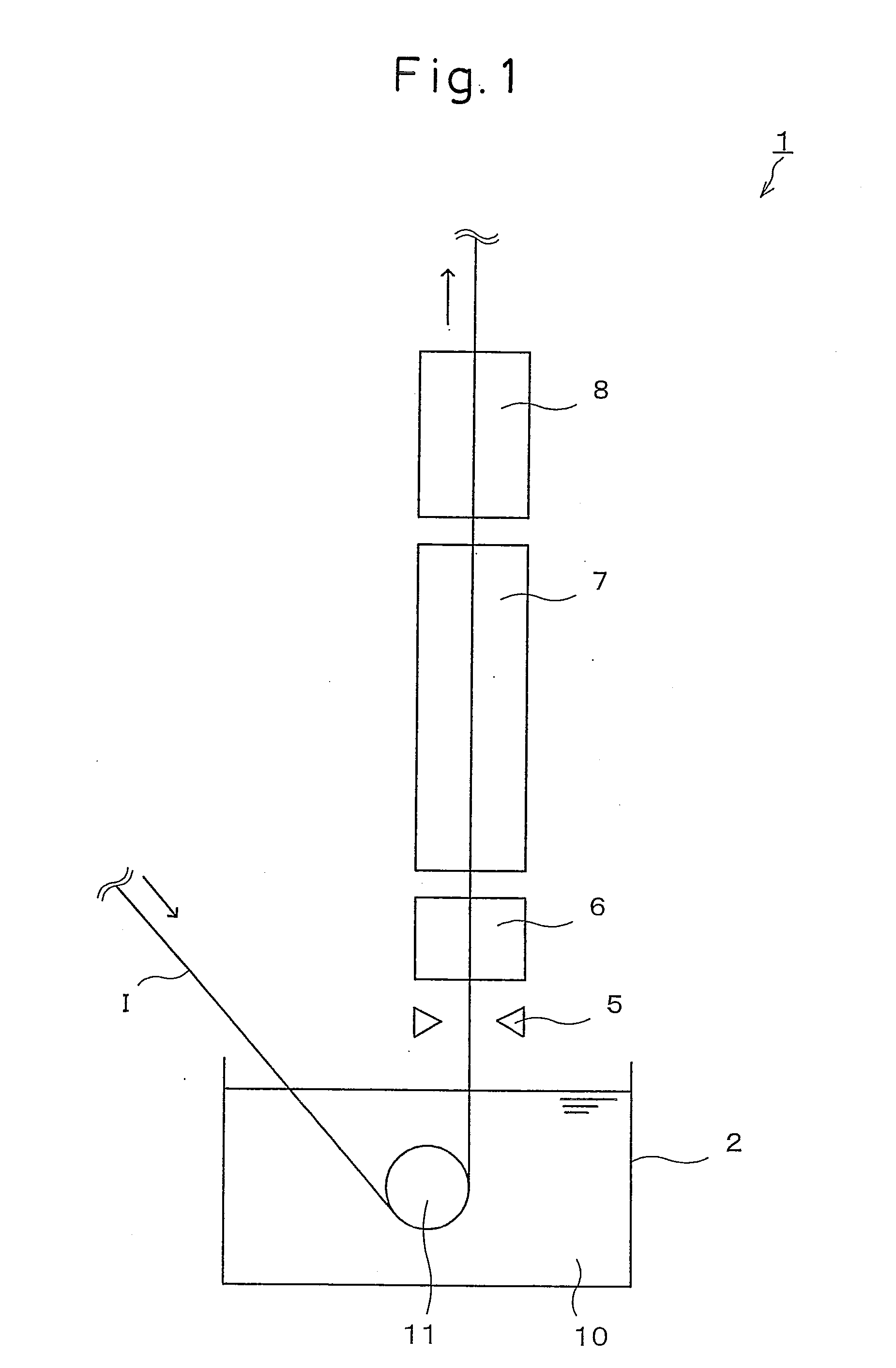
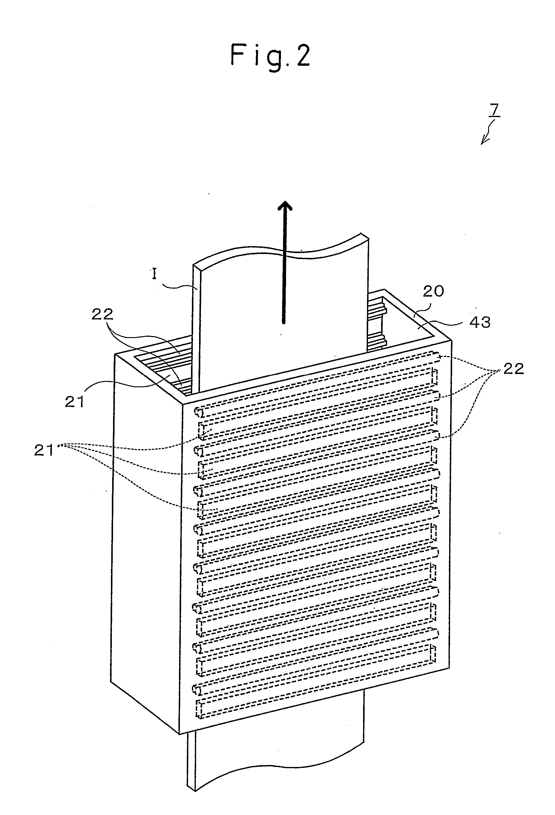
The present invention provides a production facility of hot dip galvannealed steel plate able to produce hot dip galvannealed steel plate on production conditions optimal at all times despite rapid changes in the steel type, plating deposition, and other external factors, wherein the production facility 1 of hot dip galvannealed steel plate is provided with a soaking / cooling furnace 7 for treating steel plate I running after leaving a rapid heating furnace 6 by at least one of soaking and cooling. Further, the soaking / cooling furnace 7 is configured to enable a change of the ratio in the furnace of the soaking region 15 for soaking steel plate I by soaking means 21 at a soaking temperature of 500° C. to 650° C. and the cooling region 16 for cooling the steel plate I by spray nozzles 22 by a 5° C. / sec or more average cooling rate.

Description

TECHNICAL FIELD[0001]The present invention relates to a production facility for producing hot dip galvannealed steel plate by dipping steel plate in a plating bath, then alloying it in the plating bath and a process for production of hot dip galvannealed steel plate using this facility.BACKGROUND ART[0002]When producing hot dip galvannealed steel plate using a production facility of hot dip galvannealed steel plate, first, the steel plate is dipped in a plating bath filled with 440 to 480° C. molten zinc in a plating bath tank, then gas wiping nozzles spray the two surfaces of the steel plate with gas so as to adjust the plating deposition on the surfaces of the steel plate. Next, after adjusting the deposition, the steel plate is cooled to 400 to 460° C. or so, then heated again in an alloying furnace to 480 to 650° C. to make the iron in the steel plate and the deposited zinc react to thereby obtain an iron-zinc alloy plated steel plate. In general, the alloy layer of hot dip galv...

Claims


Application Information

Patent Timeline
Patent Type & Authority Applications(United States)
IPC IPC(8): C23C2/28B05C13/00
CPCC21D1/40C21D9/56C21D9/562C21D9/573C23C2/003C23C2/26C23C2/285F27B9/28C23C2/28C23C2/00C23C2/06C23C2/00344C23C2/29C23C2/16
Inventor ONOZAWA, HAJIMEKIMURA, YOSHITAKA
Owner NIPPON STEEL CORP
Learn More