Cells and connecting channels for centrifugal partition chromatography devices

a technology of liquid liquid chromatography and connecting channels, which is applied in the field of cells and their connecting channels of centrifugal liquid liquid chromatography devices, can solve the problems of reducing the efficiency and productivity of the device, aging of the device, and increasing the dead volume, so as to increase the efficiency and productivity of the chromatography devi

Active Publication Date: 2010-08-12
INST FR DU PETROLE +1
View PDF11 Cites 12 Cited by
  • Summary
  • Abstract
  • Description
  • Claims
  • Application Information

AI Technical Summary

Benefits of technology

[0025]As described more in detail hereafter, these new cell and channel forms are likely to increase the efficiency and the productivity of chromatography devices.

Problems solved by technology

A first and double drawback of this prior art is due to the design of the cells driven through the thickness of the discs, which requires seals, generally flexible, made of Teflon par example, between each disc, thus closing each cell along the plane of the disc, therefore perpendicular to the main axis of each cell.
Even if the cell has rounded shapes to facilitate dispersion homogeneity for a better matter exchange between the two phases, the bond lines create with the cell right angles that are not favourable to homogeneous dispersion of the liquids.
Finally, these flexible bond lines subjected to continuous liquid pressure variations deform over time and they modify the geometry of the cells, hence aging of the device.
A second drawback lies in that the cells are connected to each other by a ribbon-shaped channel.
In order to limit too high pressures and, in some cases, for machining difficulty reasons, the thickness of these lines has to be increased, thus increasing the dead volumes in which the products being separated partly mix again, which reduces the efficiency and the productivity of the device.
Furthermore, if the thickness of the line is not perfectly constant over the entire length thereof, which is the case when the cells are water jet cut, a gradient of the velocity vectors of the mobile liquids (phase and compounds to be separated) appears between one face of the disc and the other, which tends to spread the compounds that are being separated, therefore to remix them and consequently to reduce the efficiency and productivity performances of the machine.

Method used


Image

  • Cells and connecting channels for centrifugal partition chromatography devices
  • Cells and connecting channels for centrifugal partition chromatography devices
  • Cells and connecting channels for centrifugal partition chromatography devices

Examples


Embodiment Construction

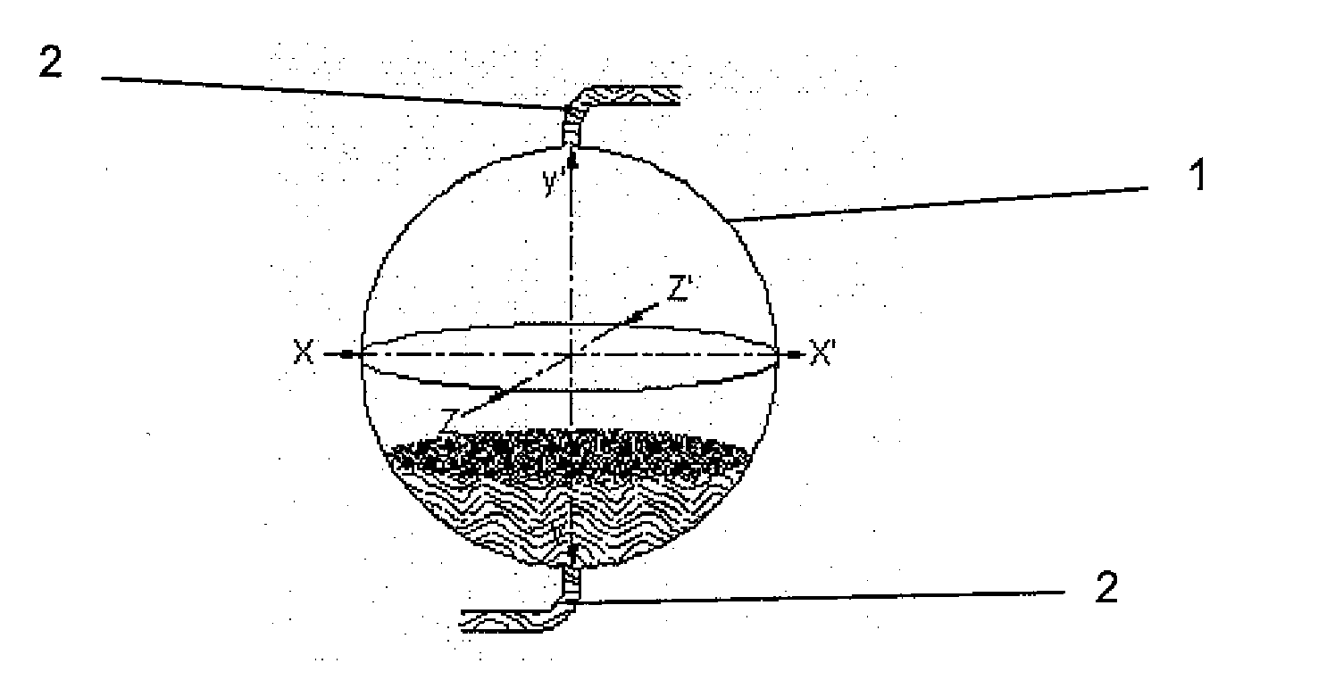
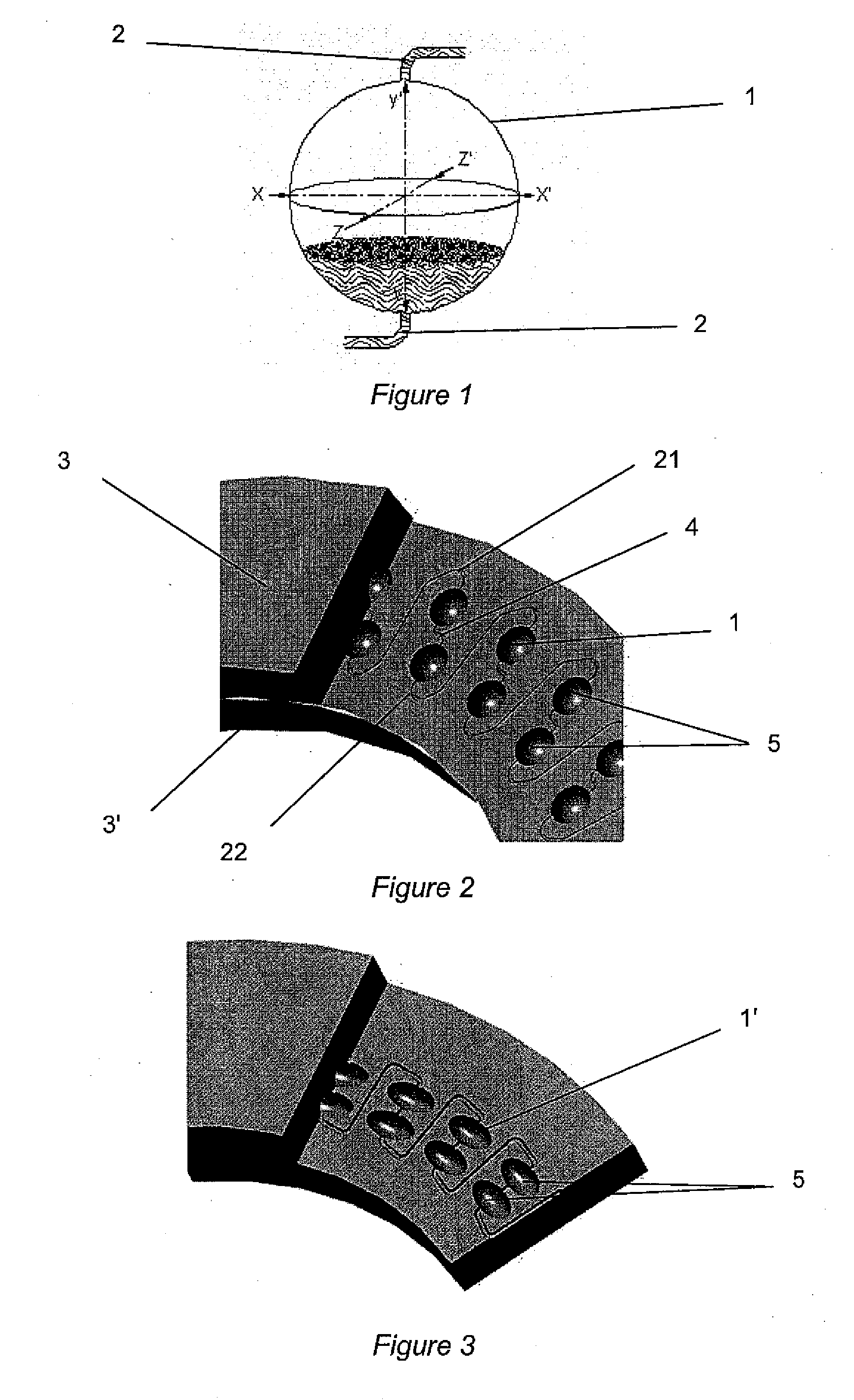
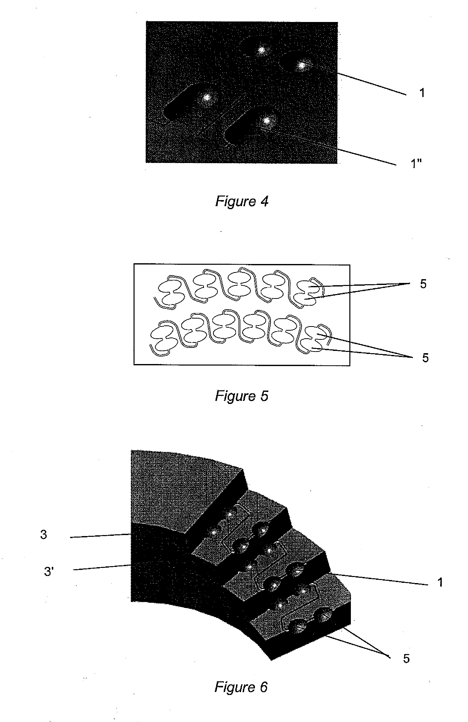
[0032]FIG. 1 illustrates a cell (1) according to the invention. The base of this cell (1) has a revolution geometry. The shape of the cells according to the invention can thus range from spheres to spheroids to other similar revolution shapes by modifying the respective length ratios of axes X-X′, Y-Y′ and Z-Z′. Axis Z-Z′ being parallel to the main axis of rotation (8) of the disc comprising the cells illustrated in FIG. 8, axis Y-Y′ being radial with respect to the disc and axis X-X′ orthogonal to the other two axes (FIGS. 1, 2, 3, 4, 5, 6 and 7).

[0033]Such a shape, compared with the cells with angular parts of the prior art, favours better dispersion of the mobile phase in the stationary phase and, consequently, allows better matter exchange, which leads to improved separation. The axis of revolution of the shape of the cells is close to the radial direction of the discs. Preferably, the axis of revolution is in the radial direction.

[0034]Channels (2, 4) connecting these cells hav...


PUM

PropertyMeasurementUnit
geometric shape of revolutionaaaaaaaaaa
dimensionaaaaaaaaaa
dimensionsaaaaaaaaaa

Abstract

The present invention relates to cells (1) for a centrifugal partition chromatography column, consisting of stacked discs and comprising a network of three-dimensional cells interconnected in series and communicating with liquid phase circulation channels, said cells being distributed over the periphery of at least one disc driven into rotation about a main axis (8); the cells have a geometric shape of revolution about a substantially radial axis with respect to said disc and they are connected by channels (2, 4) of substantially circular, elliptical or parallelepipedic section, the main two dimensions of which are smaller than the largest cross-section of the cell.
The invention also relates to methods of manufacturing these cells.

Description

FIELD OF THE INVENTION[0001]The present invention relates to the sphere of centrifugal liquid-liquid chromatography devices, and more particularly to cells and their connecting channels for centrifugal liquid-liquid chromatography devices, and to the method of manufacturing same.BACKGROUND OF THE INVENTION[0002]A known technique for separating constituents A and B in solution in a liquid mixture consists in injecting the latter into a chromatography column subjected to a centrifugal force, intended to allow one of the liquid phases to be percolated in the other liquid phase and vice versa (CCC or CPC chromatography).[0003]In practice, as shown notably in patents FR-2,791,578, U.S. Pat. No. 4,877,523 or U.S. Pat. No. 4,857,187, this type of chromatography system comprises one or more stacks of discs driven into rotation. Each one comprises in the thickness thereof and over the entire periphery thereof a succession of cells arranged in a radial or oblique direction and connected in se...

Claims


Application Information

Patent Timeline
Patent Type & Authority Applications(United States)
IPC IPC(8): B01D15/18B23P17/04
CPCB01D15/1892Y10T29/49826G01N30/42
Inventor COUILLARD, FRANCOIS
Owner INST FR DU PETROLE
Why Eureka
Try Eureka