Water Treatment System For Surface Cleaning Apparatus

Inactive Publication Date: 2010-08-12
WATERBLASTING
View PDF98 Cites 8 Cited by
  • Summary
  • Abstract
  • Description
  • Claims
  • Application Information

AI Technical Summary

Benefits of technology

[0017]It is yet a further objective of the present invention to provide a mobile water recirculation system for surface cleaning apparatus that reduces particulate size within the recirculated water to less than 1 micron.

Problems solved by technology

Such devices require a clean supply of water for proper operation, but create wastewater by entraining solids from the cleaned surface into the used source water.
One problem associated with both low and ultra-high pressure water cleaning equipment is maintaining an adequate supply of clean water for continuous operation of the system.
Dirty or contaminated water causes numerous problems with water cleaning equipment such as excessive pump wear, clogged filters, nozzles, screens and the like.
Because the water cleaning equipment requires large volumes of water to be effective, additional equipment is needed to haul in tanks of water.
Recovery and disposal of the water is another problem facing water cleaning equipment users.
Demolition or even the mere cleaning of surfaces results in the water becoming contaminated with dirt and debris.
This problem is particularly exacerbated with ultra high pressure water cleaning equipment which breaks dirt and debris up into particles small enough to remain suspended within the water indefinitely.
However, in these systems it is typically the solid filter cake that the user is interested in recovering and not the water that was carrying the solid particles, and thus the water typically remains dirty and is discarded to the drain.

Method used


Image

  • Water Treatment System For Surface Cleaning Apparatus
  • Water Treatment System For Surface Cleaning Apparatus
  • Water Treatment System For Surface Cleaning Apparatus

Examples


Embodiment Construction

[0030]While the present invention is susceptible of embodiment in various forms, there is shown in the drawings and will hereinafter be described a presently preferred embodiment with the understanding that the present disclosure is to be considered an exemplification of the invention and is not intended to limit the invention to the specific embodiments illustrated.

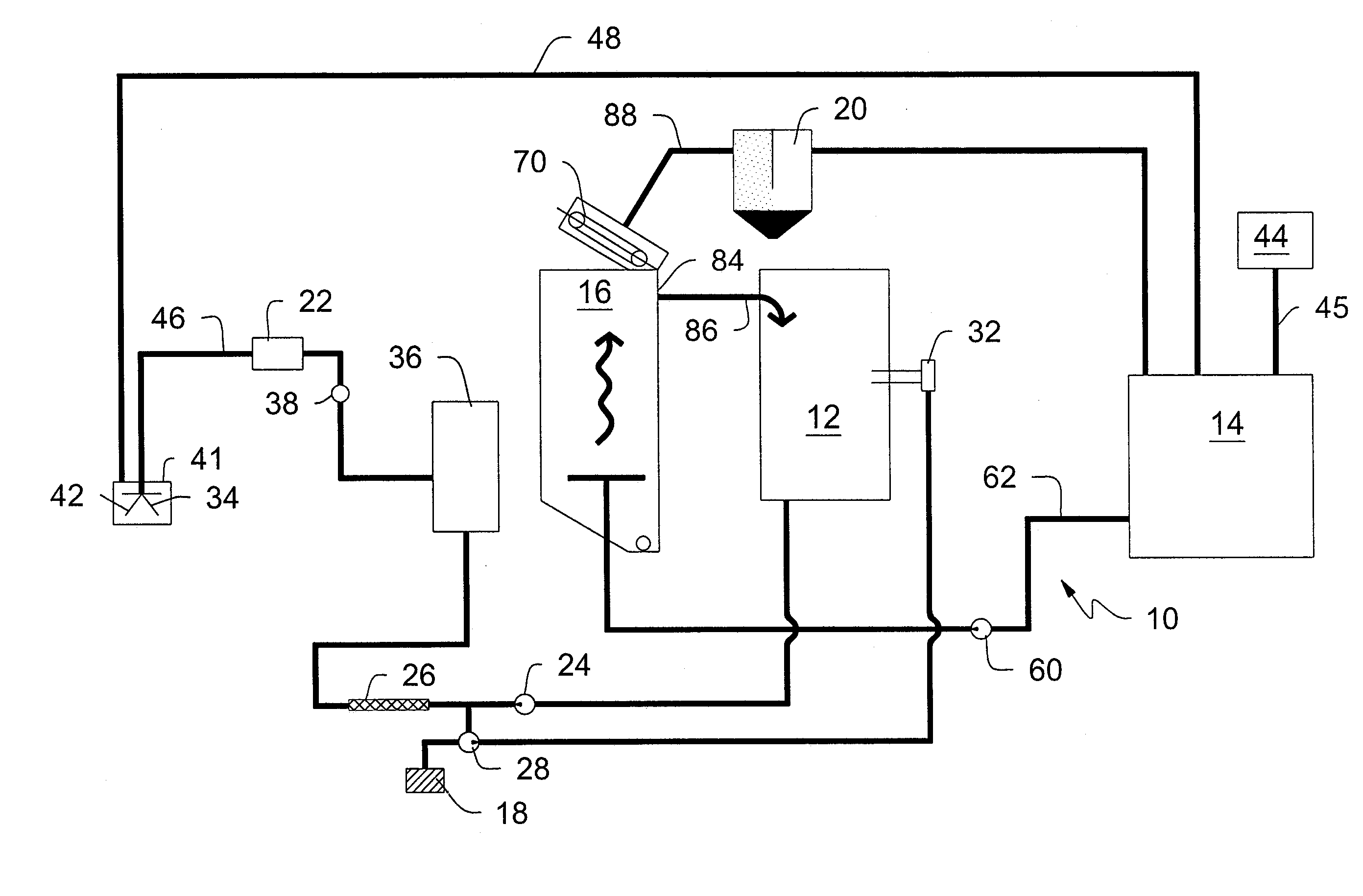
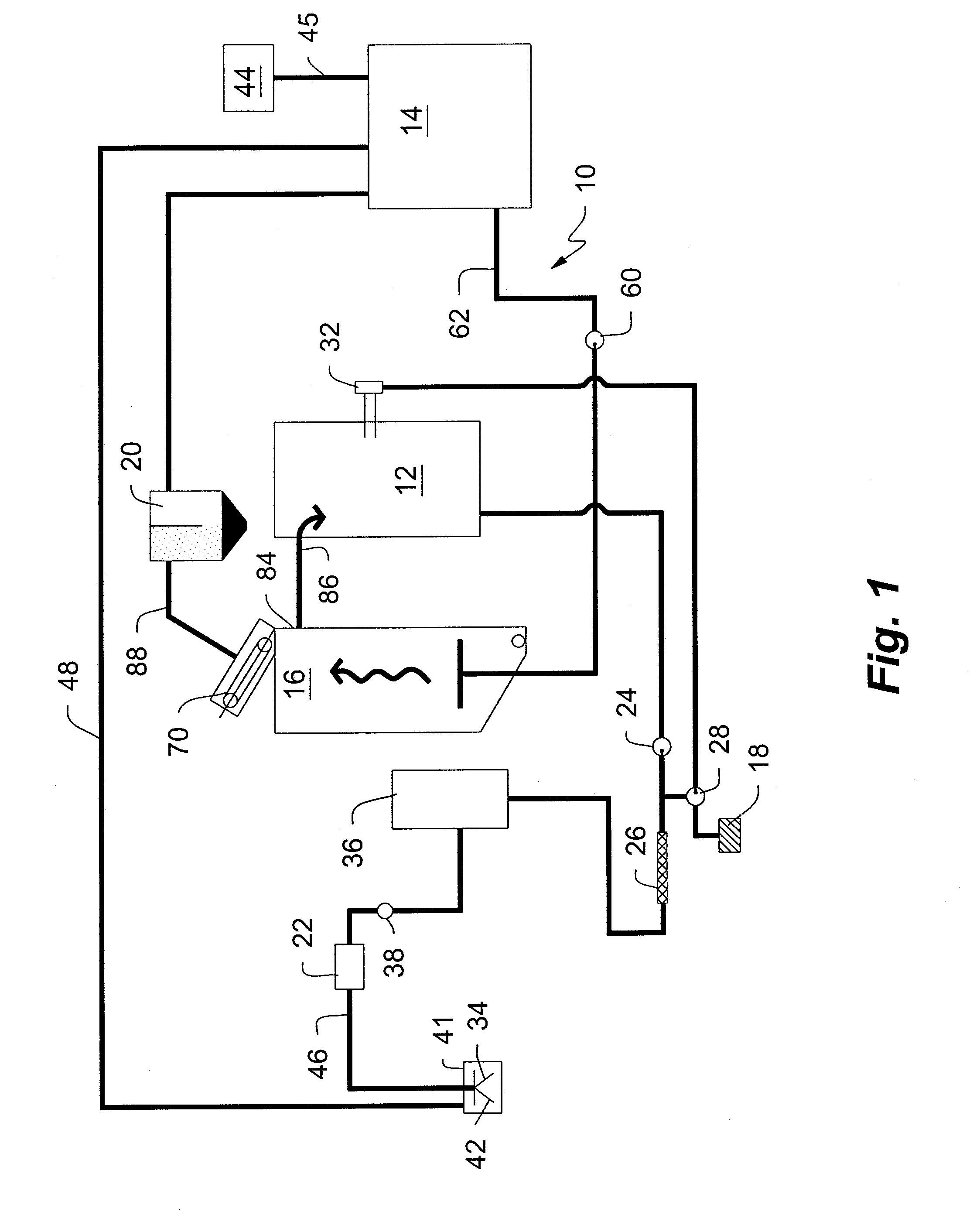
[0031]Referring generally to FIGS. 1 and 5, a mobile water recirculation system 10 for surface cleaning apparatus is illustrated. The preferred embodiment of the water recirculation system generally includes a water supply tank 12, a vacuum tank 14, a sediment tank 16, a coagulant tank 18, a muck tank 20, an ultra-high pressure pump 22, and a blast head 34. Clean water is stored in the water tank 12. Preferably, the water tank 12 has about a 2,700 gallon capacity. The water tank 12 functions not only to store substantially non-contaminated water, but also to provide a constant source of water to the ultra-high pressure w...


PUM

PropertyMeasurementUnit
Pressureaaaaaaaaaa
Diameteraaaaaaaaaa
Forceaaaaaaaaaa

Abstract

The present invention relates generally to an environmentally sensitive mobile cleaning system, and more specifically relates to a closed loop water recirculation system for high or ultra-high pressure mobile cleaning apparatus. The system includes a water tank sized to contain an established volume of fluid sufficient to circulate through the system, a pump to pressure the fluid to a cleaning head, a vacuum system to return the contaminated fluid to the system, and a filter means to remove the contaminants from the fluid so that clean fluid can be reintroduced to the cleaning head. The method comprises the steps of increasing the pressure of a fixed volume of fluid in a closed-loop system, jetting or blasting the surface with the pressurized fluid, vacuuming the blasted fluid into the system, and removing the contaminants from the fluid.

Description

CROSS REFERENCE TO RELATED APPLICATIONS[0001]This application is a continuation in part and claims the priority of U.S. Patent Application No. 61 / 147,158, entitled “Mobile Water Recirculation System For Surface Cleaning Apparatus”, filed Jan. 26, 2009, the contents of which are incorporated herein in their entirety. This application is related to U.S. Pat. No. 7,255,116, entitled “Stripe Removal System”, issued Aug. 14, 2007, U.S. patent application Ser. No. 11 / 340,738, entitled, “Transportable Holding Tank For Stripe Removal System”, filed Jan. 26, 2006, and U.S. patent application Ser. No. 11 / 340,104, entitled “Mobile Mark Removal System”, filed Jan. 26, 2006, the contents of which are incorporated herein by reference.FIELD OF INVENTION[0002]The present invention generally relates to water treatment systems, and more particularly to a closed loop water treatment system that is particularly suited for surface cleaning apparatus.BACKGROUND INFORMATION[0003]Water treatment describes ...

Claims


Application Information

Patent Timeline
IPC IPC(8): C02F9/08B01D21/28C02F1/52B01D33/82B01D33/48
CPCC02F1/004C02F1/24C02F2201/008C02F1/5227C02F1/5236C02F1/34Y02A20/152
Inventor CROCKER, JAMES P.
Owner WATERBLASTING
Why Eureka
Try Eureka