
Piezoelectric transducer device

a transducer and piezoelectric technology, applied in the direction of instruments, liquid/fluent solid measurement, generators/motors, etc., can solve the problems of mechanical deformation of materials, complicating the construction and assembly of speakers, etc., and achieves good damping characteristics and easy assembly.

Active Publication Date: 2010-08-12
AXSENSOR AB
View PDF8 Cites 4 Cited by
  • Summary
  • Abstract
  • Description
  • Claims
  • Application Information

AI Technical Summary

Benefits of technology

[0004]It is an object of the present invention to at least partly overcome these problems, and to provide an improved piezoelectric device, which device in particular is easy to assemble and further may have good damping characteristics.
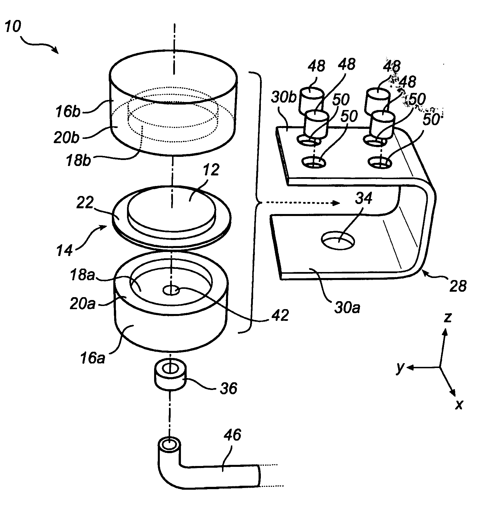
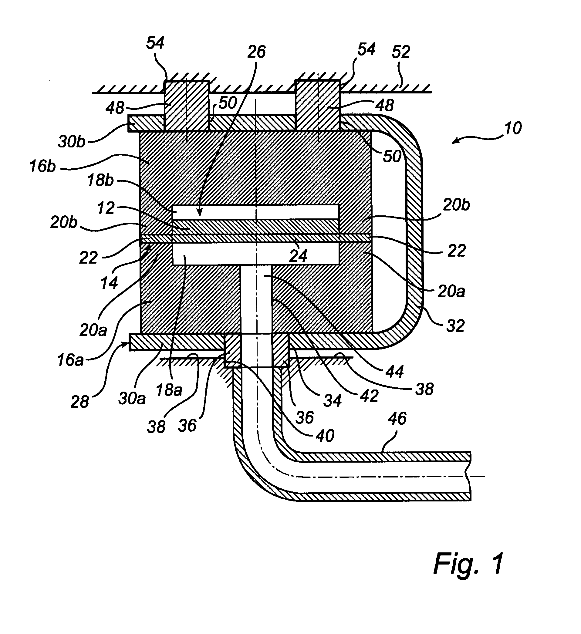
[0007]Thus, in the present invention, a single member (i.e. the clamp) is enough to constrict or hold the two elastic damping elements together, which simplifies the construction and assembly of the transducer element. Further, by securing the peripheral portion of the acoustic membrane between the two elastic damping elements, good damping of the acoustic membrane may be achieved. Further, the clamp may be resilient to allow the two elastic damping elements to shrink or expand (due to for instance environmental conditions), to maintain the device functionality even in harsh conditions. The resilient property may be achieved by appropriately dimensioning and / or shaping the clamp and / or selecting a suitable material of the clamp.
[0009]In one embodiment, the clamp is substantially U-shaped, wherein the two surfaces are two arms connected by a linking portion. For the U-shaped clamp, the above resilient property may easily be obtained, and the two elastic damping parts may easily be mounted and received in it. Alternatively, the clamp may have the shape of an elongated O, wherein the two surfaces are connected by two linking portions.
[0011]In one embodiment, the transducer device further comprises at least one further elastic damping element for attaching the rest of the transducer device to an external base. The further elastic damping element(s) may absorb unwanted vibrations and prevent them from being transferred to and from the rest of the transducer device. The further elastic damping elements may be fitted in holes in the clamp, for instance in the above mentioned through opening (in which case the further elastic damping element preferably is ring-shaped to maintain the acoustic communication), or in a dedicated hole. Alternatively, the further elastic damping elements may be attached (e.g. glued) to the outside of the clamp. The former variant is advantageous in that no gluing or the like may be necessary.
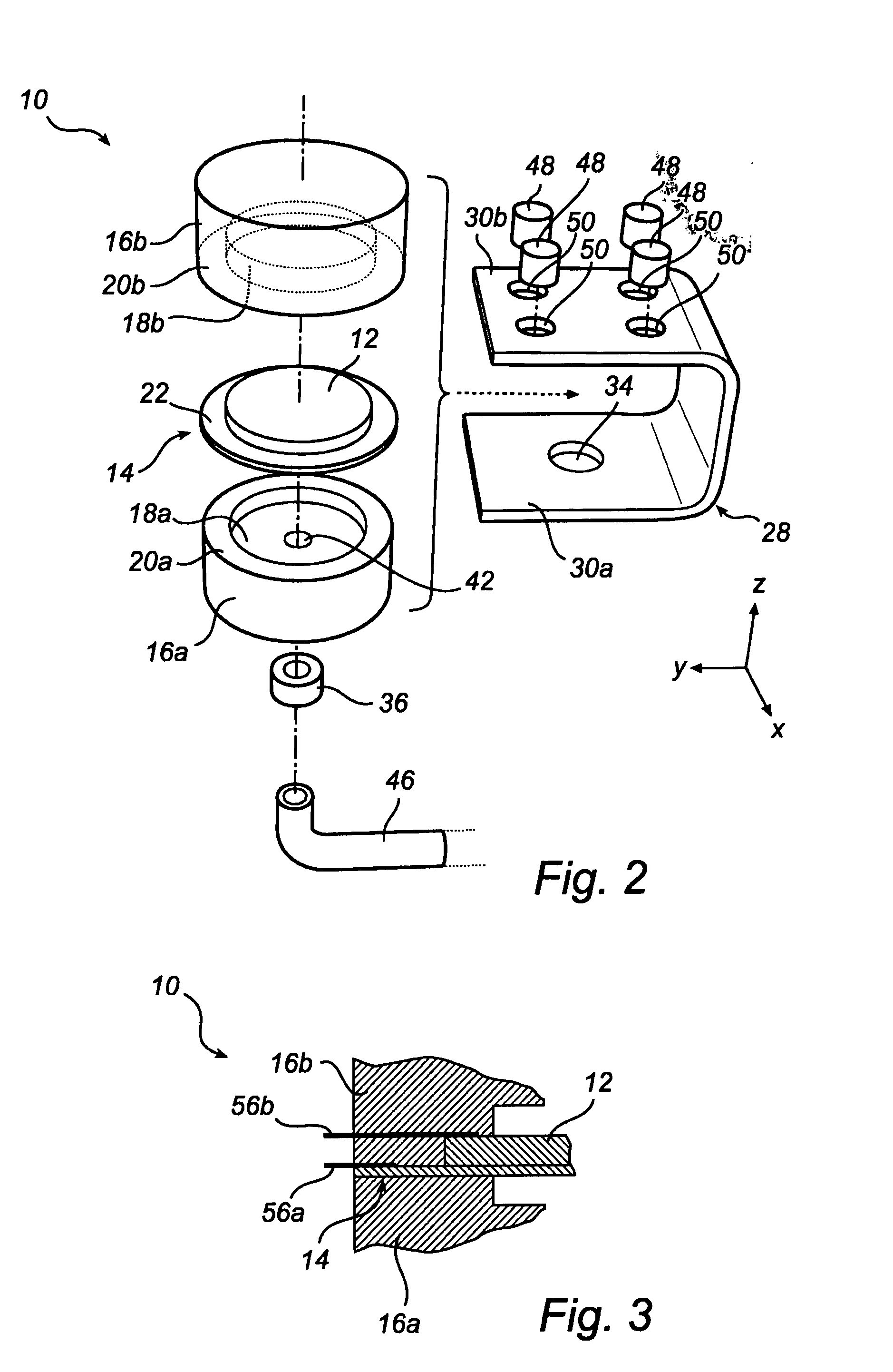
[0013]In one embodiment, the peripheral portion of the acoustic membrane includes a vibration node of the acoustic membrane. A vibration node is a point along a non-secured membrane where the amplitude when the membrane vibrates is minimal. This may further enhance the damping of the acoustic membrane.
[0014]In one embodiment, each of the two opposed elastic damping elements comprises a recess, the two recesses together forming a cavity for accommodating the non-supported portion of the membrane. Thus, the two opposed elastic damping elements may more or less enclose the acoustic membrane and piezoelectric element, to prevent or reduce transfer of unwanted vibrations, while each non-recessed portion facing the acoustic membrane may be adapted to secure the peripheral portion of the acoustic membrane. In this embodiment, when using the above waveguide, the elastic damping element next to the through opening in the clamp should have an opening to maintain the acoustic communication between the acoustic membrane and the waveguide. In an alternative embodiment, the two opposed elastic damping elements may have an annular or ring shape.

Problems solved by technology

Conversely, a voltage applied over the material causes a mechanical deformation of the material.
However, in this solution, means are required to fasten the tightening member to the supporting member, complicating the construction and assembly of the speaker.

Method used


Image

  • Piezoelectric transducer device
  • Piezoelectric transducer device
  • Piezoelectric transducer device

Examples


Embodiment Construction

[0020]FIGS. 1 and 2 illustrate a transducer device 10 according to an embodiment of the present invention. The transducer device 10 is generally adapted to convert electrical signals to acoustic signals, and vice versa, i.e. it is an electro-acoustic transducer.

[0021]The transducer device 10 comprises a piezoelectric element 12 centrally mounted on one side of an acoustic membrane 14. The piezoelectric element 12 and acoustic membrane 14 are preferably circular as shown in FIG. 2, but may have other shapes as well, for instance rectangular. The piezoelectric element 12 may for instance be made of piezo-crystal, while the acoustic membrane 14 may be made of thin metal, for instance brass or stainless steel or the like. The material selection depends among other things on the wanted acoustic characteristics and expected operating environment. The piezoelectric element 12 may be mounted on the acoustic membrane 14 by gluing, e.g. Further, the diameter of the piezoelectric element 12 ma...


PUM

PropertyMeasurementUnit
Timeaaaaaaaaaa
Electrical conductoraaaaaaaaaa
Elasticityaaaaaaaaaa

Abstract

The present invention relates to a transducer device (10), comprising: an acoustic membrane (14); a piezoelectric element (12) mounted to the acoustic membrane; two oppositely arranged elastic damping elements (16a, 16h) between which a peripheral portion (22) of the acoustic membrane is sandwichably supported; and a clamp (28) having two surfaces (30a, 30b) between which the two elastic damping elements are clamped so that the two elastic damping elements are pressed together, whereby the peripheral portion of the acoustic membrane is secured between the two elastic damping elements. The present invention also relates to a method of assembling such a transducer device.

Description

FIELD OF THE INVENTION[0001]The present invention relates to a piezoelectric transducer device. The present invention also relates to a method of assembling such a piezoelectric transducer device.BACKGROUND OF THE INVENTION[0002]Piezoelectricity is the voltage generated over some materials, e.g. some crystals, when they are subjected to mechanical deformation. Conversely, a voltage applied over the material causes a mechanical deformation of the material. It is well known to use this piezoelectric principle in many applications, such a piezoelectric pressure sensors, microphones, loudspeakers, actuators, and other transducers.[0003]An example of a piezoelectric transducer device, namely a piezoelectric speaker, is disclosed in GB1310853. The piezoelectric speaker in GB1310853 includes a circular piezoelectric element mounted on a thin circular diaphragm. The thin circular diaphragm is supported at its circumference on a supporting member, which is a portion of a housing, and clamped...

Claims


Application Information

Patent Timeline
IPC IPC(8): G10K9/122H04R31/00
CPCG01F23/2962G01F23/2968Y10T29/49005H04R17/00G10K11/004G10K9/122
Inventor BOSTROM, JAN
Owner AXSENSOR AB
Learn More