Anomaly monitoring device

a monitoring device and anomaly technology, applied in the direction of measurement devices, electrical testing, instruments, etc., can solve the problems of difficult wiring anomaly judgment, erroneous detection of anomalies, and difficulty in estimating the number of pulses for each phase, so as to improve the accuracy of anomaly detection and increase the space or cost of the devi

Active Publication Date: 2010-08-12
FUJI ELECTRIC CO LTD
View PDF5 Cites 35 Cited by
  • Summary
  • Abstract
  • Description
  • Claims
  • Application Information

AI Technical Summary

Benefits of technology

[0037]Hence an object of the invention is to provide a highly reliable anomaly monitoring device, which is capable of detecting various anomalies which cannot be detected by conventional technologies.
[0059]In particular, additional provision of an AD conversion portion is not necessary, so that there are no concerns of increased device space or cost, and in addition detection of breaks in a single line among two differential signal lines is possible, so that anomaly detection precision can be improved.

Problems solved by technology

Hence depending on the sampling timing, the intermediate voltage levels Vs1 and Vs2 may be detected transiently even during normal operation, so that there is the concern that an anomaly may be erroneously detected as a result.
For example, when the motor is rotating, numbers of pulses corresponding to the rotation speed are measured as A phase signals and B phase signals; but when the signal line for one of the phases breaks or comes into contact with the power supply line or ground line, errors occur in the number of pulses for each phase.
Next, problems with these conventional technologies are explained.
However, during operation of the motor, wiring anomaly judgment is difficult, and even when wiring is normal there is the concern that an erroneous judgment of an anomaly may be made.
If at such times the sampling timing of the AD converter on the processing unit side happens to coincide with the time at which the output signal from the encoder changes, an intermediate voltage level is detected continuously, as described above, and so there are cases in which it is erroneously judged that an anomaly has occurred, even though the wiring system is normal.
In order to avoid such erroneous judgments and enhance the reliability of the device, use of a fast AD converter with a short sampling timing period is effective; but fast AD converters are generally expensive, and so there is the problem that the device cost is increased.
On the other hand, in the second conventional technology, due to the principle of anomaly detection based on the numbers of pulses for two phases, anomaly detection is not possible in a state in which the motor is stopped.
Hence means of anomaly detection while the motor is stopped must be separately prepared, and this results in increased costs.
Further, if the first conventional technology and the second conventional technology are combined, then an anomaly detection device can be configured which can be employed both when the motor is operating and when the motor is stopped; however, anomaly detection is not possible in cases such as the following.
In this case, the anomaly can only be detected when output signals from the encoder appear due to operation of the motor; and detection is not possible merely by comparing numbers of pulses, as in the second conventional technology.
In addition to the above, there are other cases as well in which for other reasons, no difference occurs in the number of pulses during occurrence of an anomaly, so that the anomaly cannot be detected.

Method used


Image

  • Anomaly monitoring device
  • Anomaly monitoring device
  • Anomaly monitoring device

Examples


first embodiment

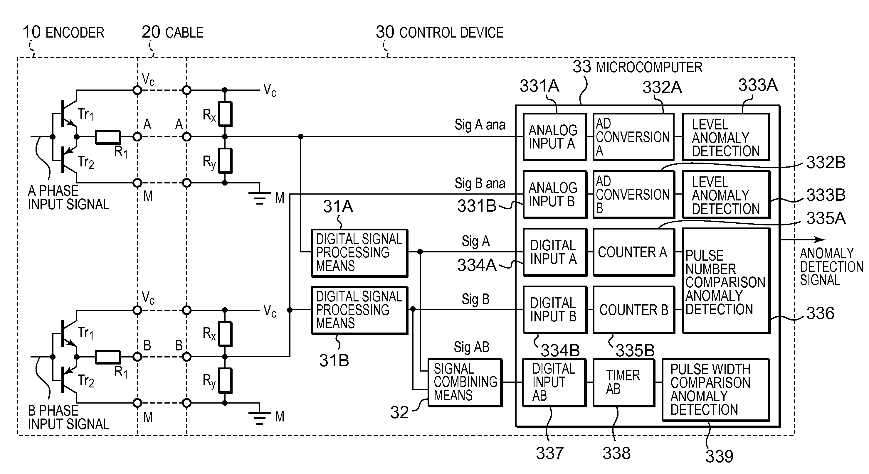
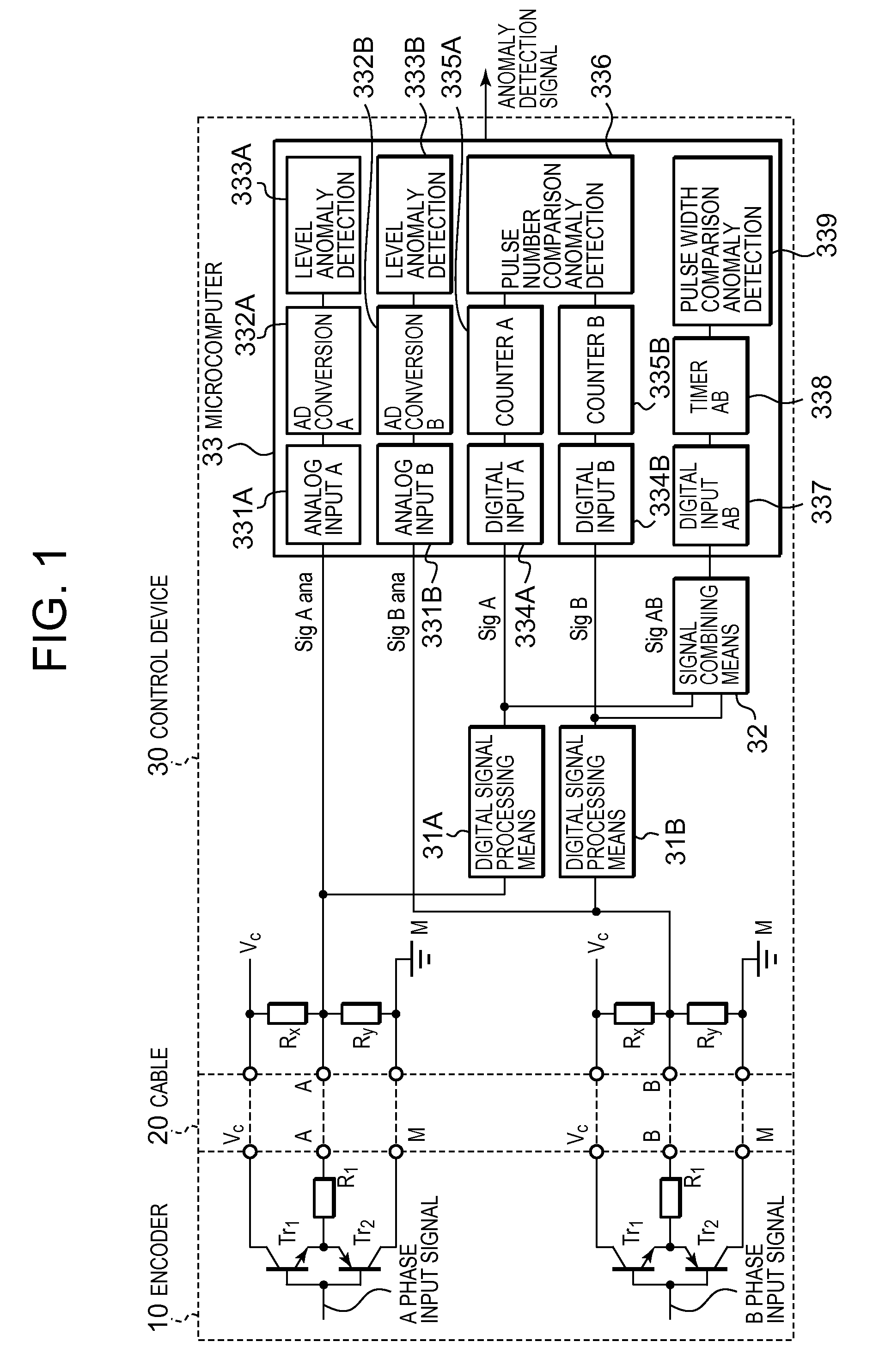
[0088]FIG. 1 is a circuit diagram showing the invention. In FIG. 1, 10 is an encoder which outputs analog signals with two phases, different by 90°; is a cable, including power supply lines, signal lines, and ground lines; and 30 is a control device which processes output signals of the encoder 10 and detects anomalies of the encoder 10 anomalies of the wiring system including the cable 20.

[0089]The encoder 10 includes an optical sensor which generates two relative position detection signals (A phase signals and B phase signals) with phase differing by 90°. The rotation member and the optical sensor are omitted from the drawing.

[0090]The A phase signals and B phase signals are respectively input to the bases of transistors Tr1, Tr2 with a complementary configuration. Here, the processing circuits for A phase signals and for B phase signals have the same configuration, and in addition to the complementary configuration of this embodiment, a complementary configuration such as that of...

third embodiment

[0150]Next, FIG. 10 is a circuit diagram showing the invention.

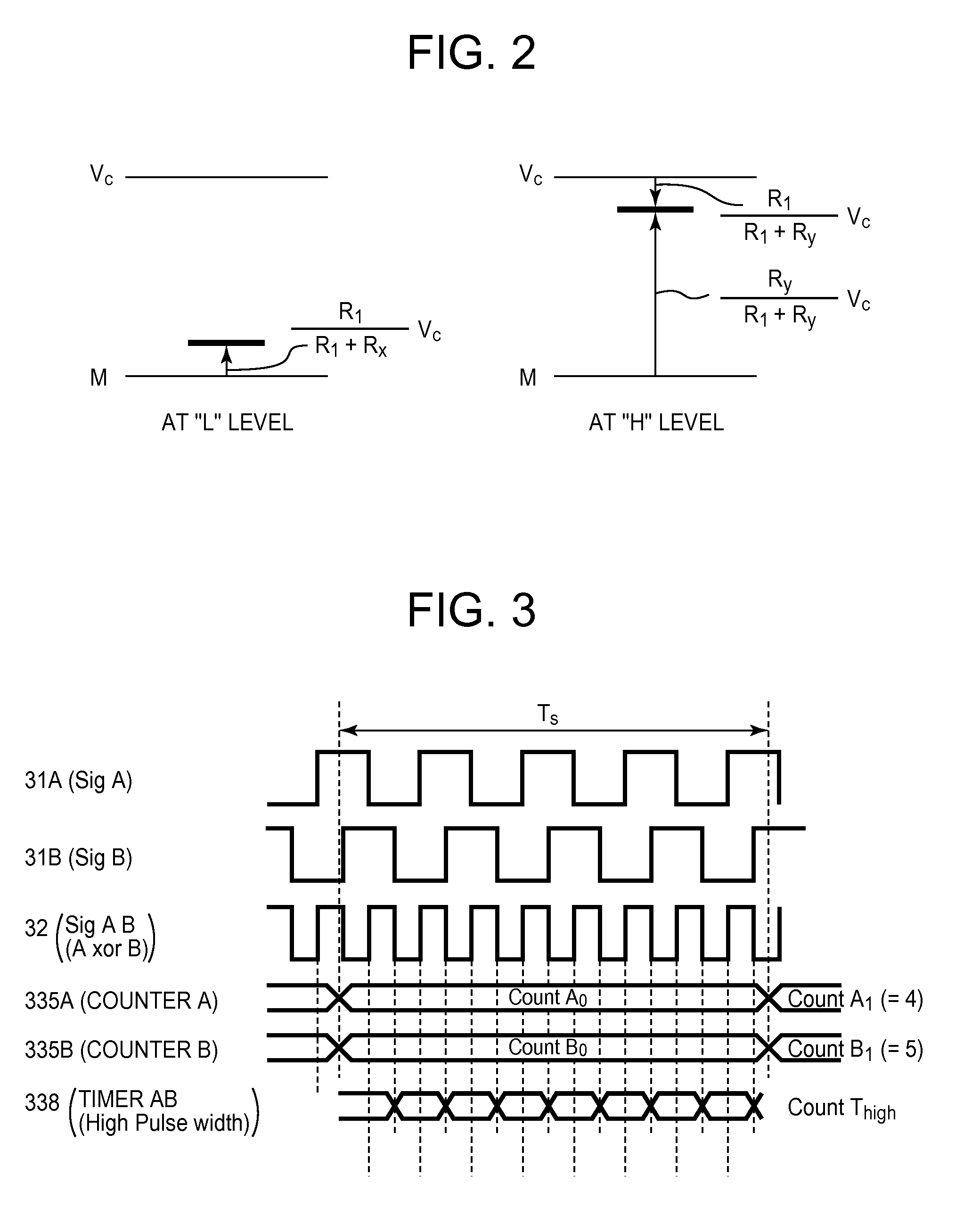
[0151]In the above-described first and second embodiments, when the pulse width comparison anomaly detection portion 339 detects anomalies based on a timer value (pulse width), the signal combining device 32 must combine the A phase and B phase digital signals SigA, SigB, with different phases, to create the combined signal SigAB. However, as is clear from FIG. 3 and elsewhere, the “H” level pulse width of the combined signal SigAB is ½ the “H” level pulse widths of the original digital signals SigA and SigB. Hence when the rotation member rotates rapidly, the “H” level pulse width of the combined signal SigAB becomes short, and due to constraints on the microcomputer clock resolution, if the pulse width becomes shorter than the time intervals measured by the timer, measurement becomes impossible. In addition, in the first and second embodiments it is not possible to create the combined signal within the microcomputer, a...

second embodiment

[0174]The position for dual configuration of the two microcomputers 311X, 311Y, and the mode of communication between the microcomputers 311X, 311Y, can be selected arbitrarily, similarly to FIG. 9.

[0175]In this embodiment also, the data comparison devices 313X, 313Y compare data received by the communication devices 312X, 312Y from the other microcomputer with their own anomaly detection results, with the voltage levels of analog signals, with the number of pulses of digital signals, and with pulse widths. And, when there are differences between these data, and when the differences between the voltage levels, numbers of pulses, and pulse widths exceed prescribed threshold values, an anomaly detection signal 1 or anomaly detection signal 2 is output. By this means, the functions of the microcomputers 311X, 311Y can be diagnosed.

[0176]Here, the anomaly detection signal 1 and anomaly detection signal 2 may include the anomaly detection results of the level anomaly detection itself, of...


PUM


Abstract

In an anomaly monitoring device, in which an output signal from an encoder is input as an analog input signal via a wiring system, for detecting anomalies in the encoder or the wiring system, provided are a voltage level based device, a pulse number based device and a pulse width based device. The voltage level based device detects anomalies when the voltage level of the analog input signal exists within a prescribed range. The pulse number based device detects anomalies when the difference in the numbers of pulses of digital signals corresponding to the analog input signals is equal to or greater than a prescribed threshold value. The pulse width based device detects anomalies when the pulse width of the digital signals, measured from a combined signal of the digital signals or each of the digital signals, is different from the pulse width in a past control period.

Description

CROSS-REFERENCE TO RELATED APPLICATION[0001]This application claims priority to and the benefit of Japanese Patent Applications No. 2009-027517 (filed on Feb. 9, 2009), No. 2009-049375 (filed on Mar. 3, 2009) and No. 2009-116207 (filed on May 13, 2009), the disclosure of which are incorporated herein by reference in its entirety.BACKGROUND OF THE INVENTION[0002]1. Field of the Invention[0003]This invention relates to an anomaly monitoring device which detects anomalies of pulse encoders (hereafter simply called “encoders”) and anomalies of wiring systems to implement safety functions in, for example, a power converter such as an inverter and a servo system for driving a motor.[0004]2. Description of the Related Art[0005]Inverters and servo systems which compute motor speed and rotor position from output signals of a pulse encoder mounted on the output shaft of a motor, and which feed back these computed values in variable-speed driving of the motor, are in widespread use. In such de...

Claims


Application Information

Patent Timeline
Patent Type & Authority Applications(United States)
IPC IPC(8): G01R31/02G01R31/50
CPCG01R31/024G01D5/24461G01R31/50
Inventor SATO, IKUYATAKAHASHI, HIROSHI
Owner FUJI ELECTRIC CO LTD
Why Eureka
Try Eureka