
Power-up Control for Very Low-Power Systems

a technology of power supply control and very low-power systems, applied in the direction of pulse automatic control, pulse technique, electronic switching, etc., can solve the problem that the realization of such high time constants on chips may take up too much space to be practical, and add to undesired quiescent currents in the system, so as to accurately control the level of vdd

Active Publication Date: 2010-08-12
MICROCHIP TECH INC
View PDF21 Cites 32 Cited by
  • Summary
  • Abstract
  • Description
  • Claims
  • Application Information

AI Technical Summary

Benefits of technology

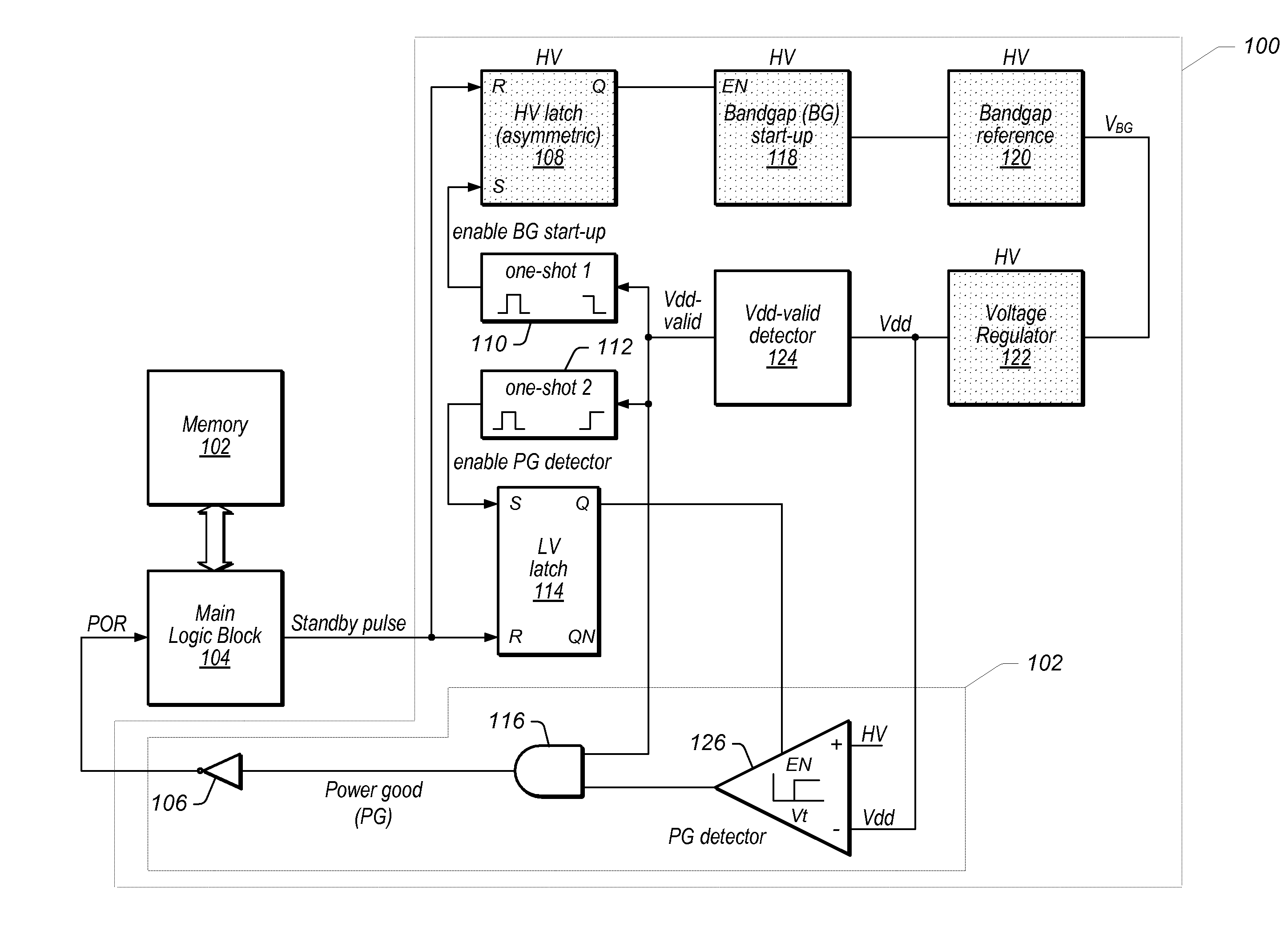
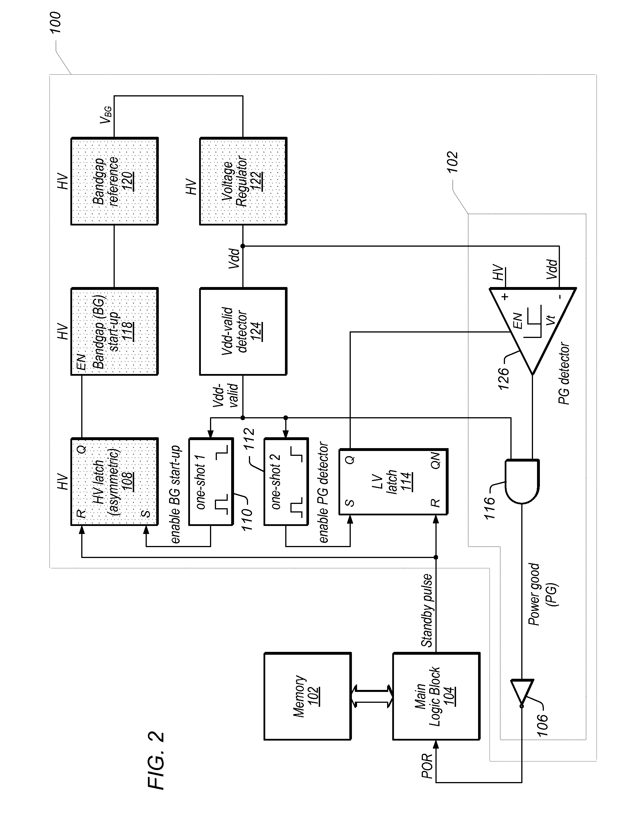
[0010]In one set of embodiments, a power-on-reset (POR) signal generation circuit may be configured to control the start-up of a bandgap reference and the generation of a POR signal in a system with a high, wide-ranging first supply voltage external to the system, and a lower second supply voltage (Vdd) generated from the first supply voltage and the bandgap reference, and regulated inside the system. The POR circuit may operate to keep the POR signal active until Vdd has reached its final level, and may be configured to exhibit the same behavior and go through the proper reset cycle if necessary every time power is turned on or off. The POR circuit may further be configured to consume only minimal sub-μA quiescent supply current, with a modest amount of current used during the power-up phase. The bandgap reference may accurately control the level of Vdd, even when the external power supply HV has large variations. The POR signal may be used to reset any selected main logic block within the system.
[0011]The start-up of the bandgap reference may be controlled and the main logic block may be held in the reset state until the internal supply voltage reaches its nominal (actual final) level. This may guarantee a proper reset of the main logic and a re-start of the bandgap reference, should the power drop below operational level then rise up to operational levels once again. Following power-up, when the main logic block is no longer in reset and is running, the circuits associated with powering up may be turned off, thereby saving supply current.

Problems solved by technology

One problem of integrating a POR circuit operated according to this technique is with the rate of the rise of the power supply, which is generally quite slow.
Realization of such high time constants on chip may take up too much space to be practical, although the same time constant may be easily realized in an external circuit.
Thus, a typical start-up circuit will always continuously consume some current, adding to undesired quiescent currents in the system.
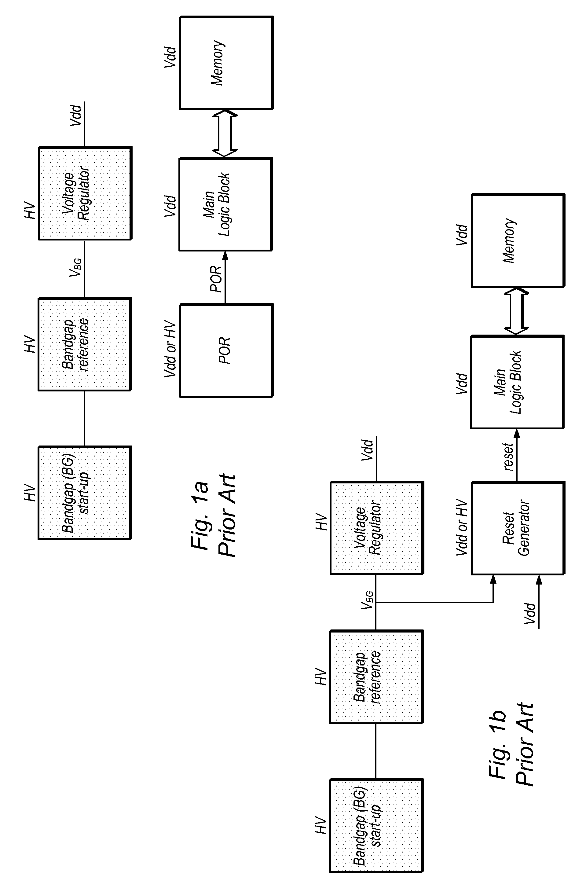
In addition, a typical Reset Generator will not operate accurately if the reference voltage (VBG) it uses has not reached its final level, which may happen if the supply voltage (Vdd) reaches the desired operating level very slowly.
In some cases, the Main Logic Block (or circuit) may be kept in the reset state with a simple POR circuit operated without the use of a bandgap reference (FIG. 1a), which may result in the POR circuit tripping at an unpredictable voltage.
Although this voltage level may be sufficient for the Main Logic Block circuits to operate, it may be too low to read an on-chip memory (such as the Memory in FIGS. 1a and 1b).
A POR circuit on the external power supply side may also effectively perform the task, but it may not be accurate enough.

Method used


Image

  • Power-up Control for Very Low-Power Systems
  • Power-up Control for Very Low-Power Systems
  • Power-up Control for Very Low-Power Systems

Examples


Embodiment Construction

[0022]As used herein, the term “nominal value” is used to denote an expected, stable value. For example, the nominal value of a first supply voltage is used to denote the final, stable value reached by the first supply voltage. While the term “nominal” typically refers to a specified theoretical value from which an actual value may deviate ever so slightly, in order to simplify references to certain voltage values detailed herein, “nominal value” is used to refer to the final, expected stable value reached by a supply voltage. For example, as used herein, when a supply voltage has a nominal value of 1.9V, it means that the supply voltage is configured to settle and reside at a value of 1.9V. Of course, the actual value of the supply voltage may deviate ever so slightly from this value, and such deviations are meant to be accounted for when using the term “nominal value”. In other words, when a first supply voltage is said to have a value that is higher by a specific difference volta...


PUM


Abstract

A power-on-reset (POR) circuit may comprise a first circuit powered by a first supply voltage and configured to generate a second supply voltage based on the first supply voltage, the second supply voltage having a nominal value lower than a nominal value of the first supply voltage. The POR circuit may also include a second circuit powered by the second supply voltage and configured to generate a POR signal. The second circuit may be configured to assert the POR signal when the second supply voltage reaches a value that is sufficiently high for the second circuit to become operational, keep the POR signal asserted until the first supply voltage reaches a second value that is higher than the nominal value of the second supply voltage by a specified difference voltage value, and deassert the POR signal once the first supply voltage reaches the second value.

Description

BACKGROUND OF THE INVENTION[0001]1. Field of the Invention[0002]This invention relates generally to the field of semiconductor circuit design, and more particularly to the design of improved power-up control in low-power systems.[0003]2. Description of the Related Art[0004]A POR (power-on-reset) signal is typically required by digital circuits such as memory elements, flip-flops, microcontrollers and central processing units to set an initial state immediately after powering on the circuit. For example, when powered on, most of the programmed or programmable type logic circuits, in particular microprocessors, must be set in a zero state or RESET state in order to insure that no undetermined logic states are present in any portion of the circuit. This signal has been traditionally generated externally, typically using an external RC circuit or simply a switch, the latter having to be manually operated in most cases.[0005]More recently, integrated POR circuits have been incorporated i...

Claims


Application Information

Patent Timeline
Patent Type & Authority Applications(United States)
IPC IPC(8): H03L7/00
CPCH03K17/20
Inventor ILLEGEMS, PAUL F.
Owner MICROCHIP TECH INC
Learn More