Multilayer coil component and method for manufacturing the same

a multi-layer coil and component technology, applied in the direction of inductances, inductances with magnetic cores, basic electric elements, etc., can solve the problems of reducing the thickness of each magnetic ceramic layer, reducing the product having a low direct current resistance, and increasing the cost of manufacturing. , to achieve the effect of reducing the magnetic permeability of the magnetic ceramic, and reducing the cost of manufacturing

Active Publication Date: 2010-08-12
MURATA MFG CO LTD
View PDF5 Cites 28 Cited by
  • Summary
  • Abstract
  • Description
  • Claims
  • Application Information

AI Technical Summary

Benefits of technology

[0026]In addition, when the ceramic containing 0.5 to 0.8 percent by weight of SnO2 is used, the effect described above can be further ensured.
[0027]In addition, when SnO2 is added, the magnetic permeability of the magnetic ceramic is decreased, and the strength is also decreased. However, when the zinc borosilicate-based low softening point crystallized glass is added, the decreases in magnetic permeability and strength can be compensated for.
[0028]In addition, according to the present invention, the average value of the diameters of pores relating to the pore area ratio of the magnetic ceramic is preferably set in the range of 0.1 to 0.6 w, and the reasons for this are that when the pore diameter is less than 0.1 μm, an acidic solution is not likely to reach the interfaces between the internal conductors and the magnetic ceramic located therearound through the side gap portion, and when the pore diameter is more than 0.6 μm, the strength of the magnetic ceramic element is decreased.
[0029]In addition, in the method for manufacturing a multilayer coil component of the present invention, since an acidic solution is allowed to permeate the magnetic ceramic element from the side surface thereof through the side gap portion and to reach the interfaces between the internal conductors and the magnetic ceramic located therearound so as to cut the bonds between the internal conductors and the magnetic ceramic located therearound at the interfaces therebetween, even when the end surfaces of the magnetic ceramic element are covered with the external electrodes, the acidic solution can reliably reach the interfaces between the internal conductors and the magnetic ceramic located therearound by permeation, and hence stresses at the interfaces between the internal conductors and the magnetic ceramic l...

Problems solved by technology

Incidentally, in a multilayer coil component obtained by simultaneous firing of a magnetic ceramic and internal conductors, an internal stress generated by the difference in coefficient of thermal expansion between magnetic ceramic layers and internal conductor layers degrades magnetic characteristics of the magnetic ceramic and causes a problem in that the impedance value of the multilayer coil component decreases and/or fluctuates.
Hence, a problem may arise in that a product having a low direct current resistance is difficult to obtain.
In particular, in the case of a compact product, such as a pro...

Method used


Image

  • Multilayer coil component and method for manufacturing the same
  • Multilayer coil component and method for manufacturing the same
  • Multilayer coil component and method for manufacturing the same

Examples


example 1

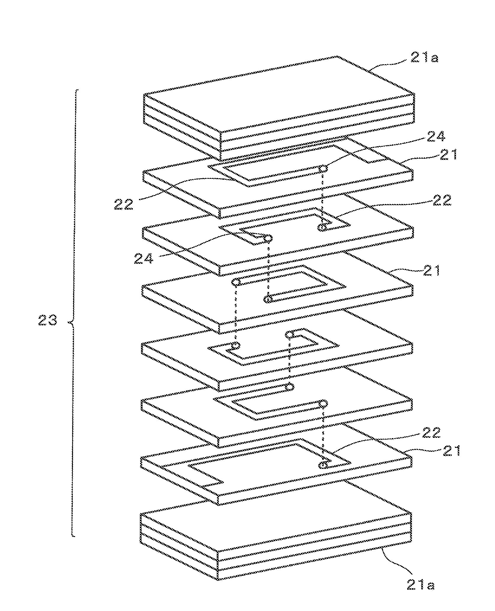
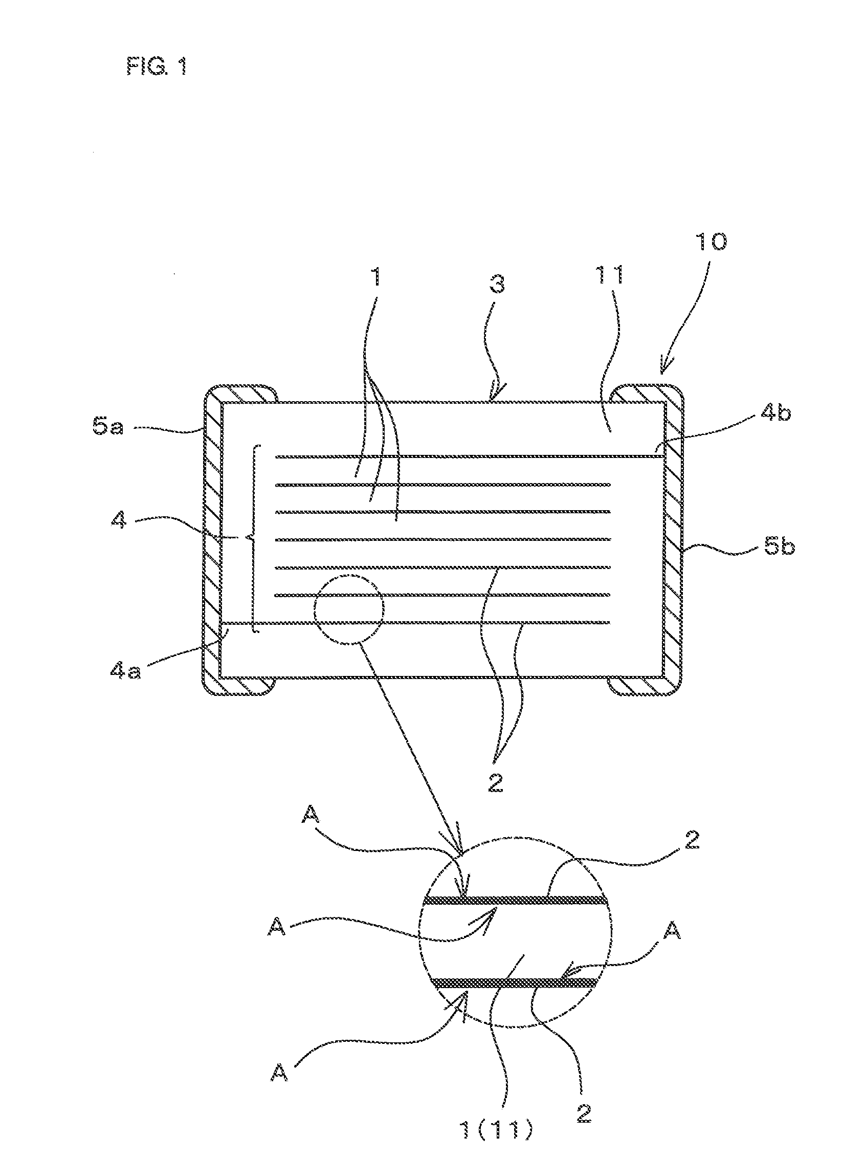
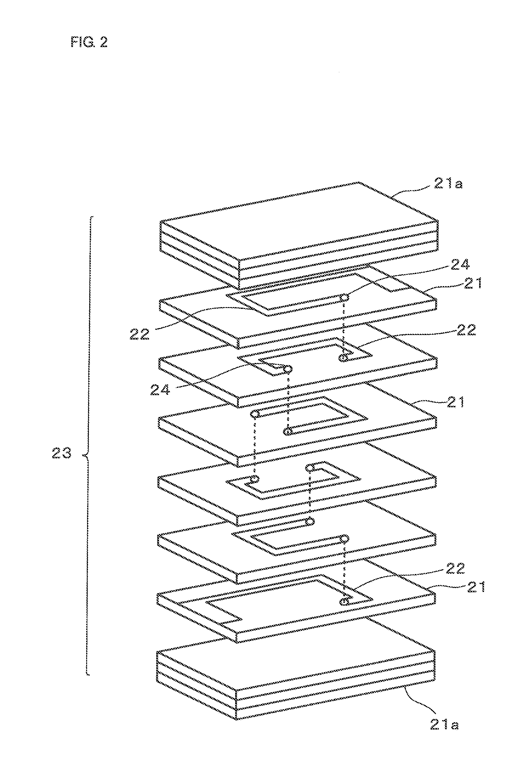
[0040]FIG. 1 is a cross-sectional view showing the structure of a multilayer coil component (e.g., multilayer impedance element in Example 1) according to one example of the present invention, and FIG. 2 is an exploded perspective view showing a manufacturing method of the multilayer coil component. This multilayer coil component 10 is manufactured through a step of firing a laminate 3 in which coil-forming internal conductors 2 primarily composed of Ag and magnetic ceramic layers 1 are laminated to each other, and a magnetic ceramic element 3 includes a spiral coil 4 therein.

[0041]In addition, a pair of external electrodes 5a and 5b is provided at two end portions of the magnetic ceramic element 3 so as to be electrically connected to two end portions 4a and 4b of the spiral coil 4, respectively.

[0042]In addition, in this multilayer coil component 10, as schematically shown in FIG. 1, no voids are present at interfaces A between the internal conductors 2 and a magnetic ceramic 11 l...

example 2

[0113]In Example 2, an example of a multilayer coil component formed using a magnetic ceramic added with a glass will be described.

[0114]A magnetic raw material was prepared in such a way that Fe2O2, ZnO, NiO, and CuO were weighed at a ratio of 48.0 mole percent, 29.5 mole percent, 14.5 mole percent, and 8.0 mole percent, and wet mixing was performed using a ball mill for 48 hours to form a slurry.

[0115]Subsequently, this slurry was dried by a spray dryer and was calcined at 700° C. for 2 hours to obtain a calcined material.

[0116]Next, after a zinc borosilicate-based low softening point crystallized glass was added to this calcined material at a ratio of 0 to 0.6 percent by weight and was then wet-pulverized by a ball mill for 16 hours, a predetermined amount of a binder was mixed, so that a ceramic slurry was obtained.

[0117]In addition, the zinc borosilicate-based low softening point crystallized glass may be added before the calcination.

[0118]The zinc borosilicate-based crystalliz...

example 3

[0137]In Example 3, an example of a multilayer coil component formed using a magnetic ceramic in which SnO2 was added to NiCuZn ferrite will be described.

[0138]After Fe2O3, ZnO, NiO, and CuO were weighed at a ratio of 48.0 mole percent, 29.5 mole percent, 14.5 mole percent, and 8.0 mole percent, SnO was weighed at a ratio of 0 to 1.25 percent by weight to the primary components (that is, at a ratio of 0 to 1.2 percent by weight of the total weight) to form a magnetic raw material, and wet mixing was performed using a ball mill for 48 hours, so that a slurry was formed.

[0139]Subsequently, this slurry was dried by a spray dryer and was calcined at 700° C. for 2 hours to obtain a calcined material.

[0140]After 0.3 percent by weight of a zinc borosilicate-based low softening point crystallized glass was added to this calcined material and was then wet-pulverized by a ball mill for 16 hours, a predetermined amount of a binder was added and mixed, so that a ceramic slurry was obtained.

[014...


PUM


Abstract

A highly reliable multilayer coil component is provided without forming voids between magnetic ceramic layers and internal conductor layers. According to the multilayer coil component, an internal stress problem is reduced, the direct current resistance is low, and fracture of internal conductors caused by the surge or the like is not likely to occur. An acidic solution is allowed to permeate a magnetic ceramic element from a side surface thereof through a side gap portion which is a region between side portions of the internal conductors and the side surface of the magnetic ceramic element and to reach interfaces between the internal conductors and a magnetic ceramic located therearound. A pore area ratio of the magnetic ceramic of the side gap portion which is located between the side portions of the internal conductors and the side surface of the magnetic ceramic element is set in the range of 6% to 28%.

Description

CROSS REFERENCE TO RELATED APPLICATIONS[0001]The present application is a continuation of International Application No. PCT / JP2008 / 065029, filed Aug. 22, 2008, which claims priority to Japanese Patent Application No. 2007-238624 filed Sep. 14, 2007, the entire contents of each of these applications being incorporated herein by reference in their entirety.BACKGROUND OF THE INVENTION[0002]1. Field of the Invention[0003]The present invention relates to a multilayer coil component having the structure in which a magnetic ceramic element includes a spiral coil therein, the magnetic ceramic element being formed by firing a ceramic laminate in which coil-forming internal conductors primarily composed of Ag and magnetic ceramic layers are laminated to each other.[0004]2. Description of the Related Art[0005]In recent years, electronic components have been increasingly required to be miniaturized, and also as for coil components, a multilayer type has been becoming a mainstream.[0006]Incident...

Claims


Application Information

Patent Timeline
IPC IPC(8): H01F5/00
CPCH01F17/0013H01F17/04H01F5/00
Inventor KONOUE, MASAHARUMAEDA, YUKIOMIZUNO, TATSUYAHASHIMOTO, HIROKIUEDA, MITSURU
Owner MURATA MFG CO LTD
Why Eureka
Try Eureka