Phase noise suppression in an optical system

Inactive Publication Date: 2010-08-12
LUXDYNE
View PDF6 Cites 8 Cited by
  • Summary
  • Abstract
  • Description
  • Claims
  • Application Information

AI Technical Summary

Benefits of technology

[0041]In another specific embodiment, at least one amplitude regenerator is a coupled amplitude regenerator. As used herein, a coupled amplitude regenerator means an amplitude regenerator in which there is some coupling between the two signal paths within the amplitude regenerator. In contrast, the two signal paths of a non-coupled amplitude regenerator are not coupled to one another within the amplitude regenerator. A coupled amplitude regenerator provides the benefit over an uncoupled one that it is more readily implemented via limiting amplification (called discriminative amplification by Grigoryan). Limiting amplification tends to be faster than non-linear attenuation, which is the primary operating principle in connection with non-coupled amplitude regenerators. On the other hand, benefits of a non-coupled amplitude re

Problems solved by technology

Real-world optical transmission systems are not ideal, however, and the signal deviates from the idealized representation given in the diagram 1-6.
The scheme benefits of simple construction, but simulation experiments carried

Method used


Image

  • Phase noise suppression in an optical system
  • Phase noise suppression in an optical system
  • Phase noise suppression in an optical system

Examples


Embodiment Construction

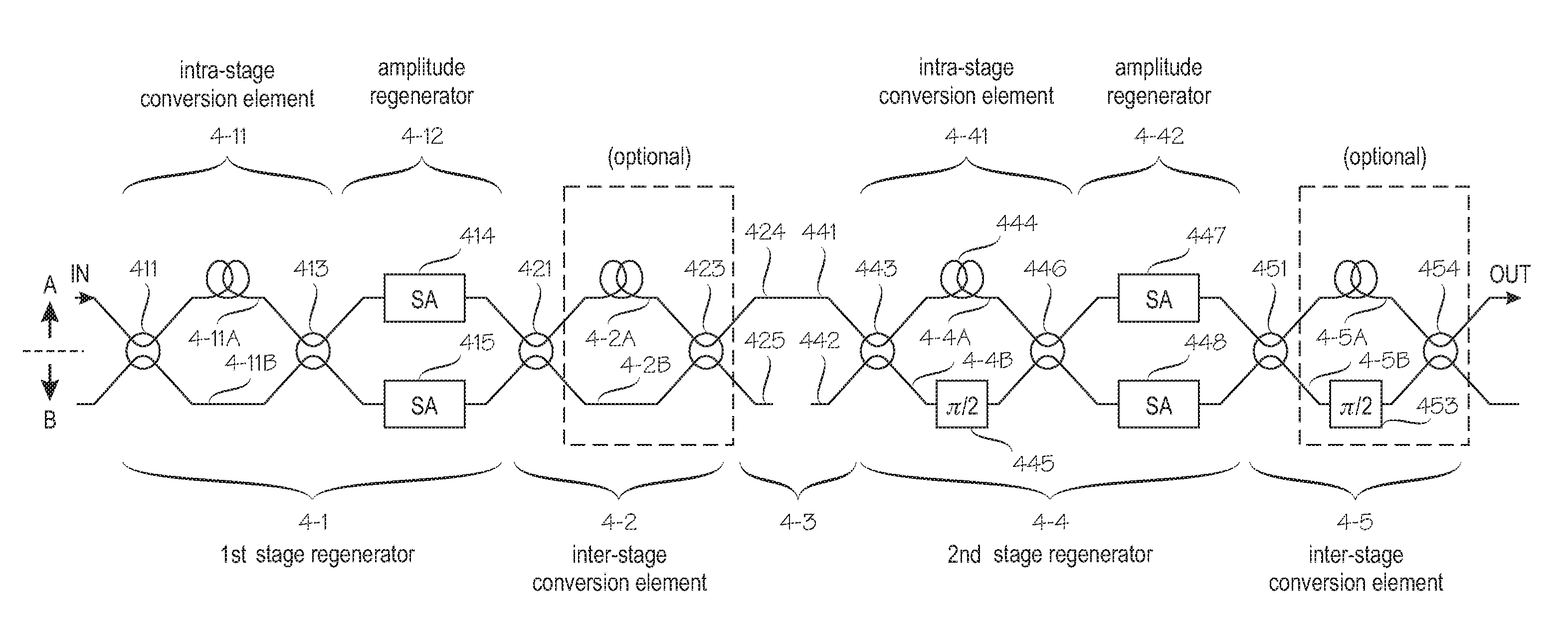
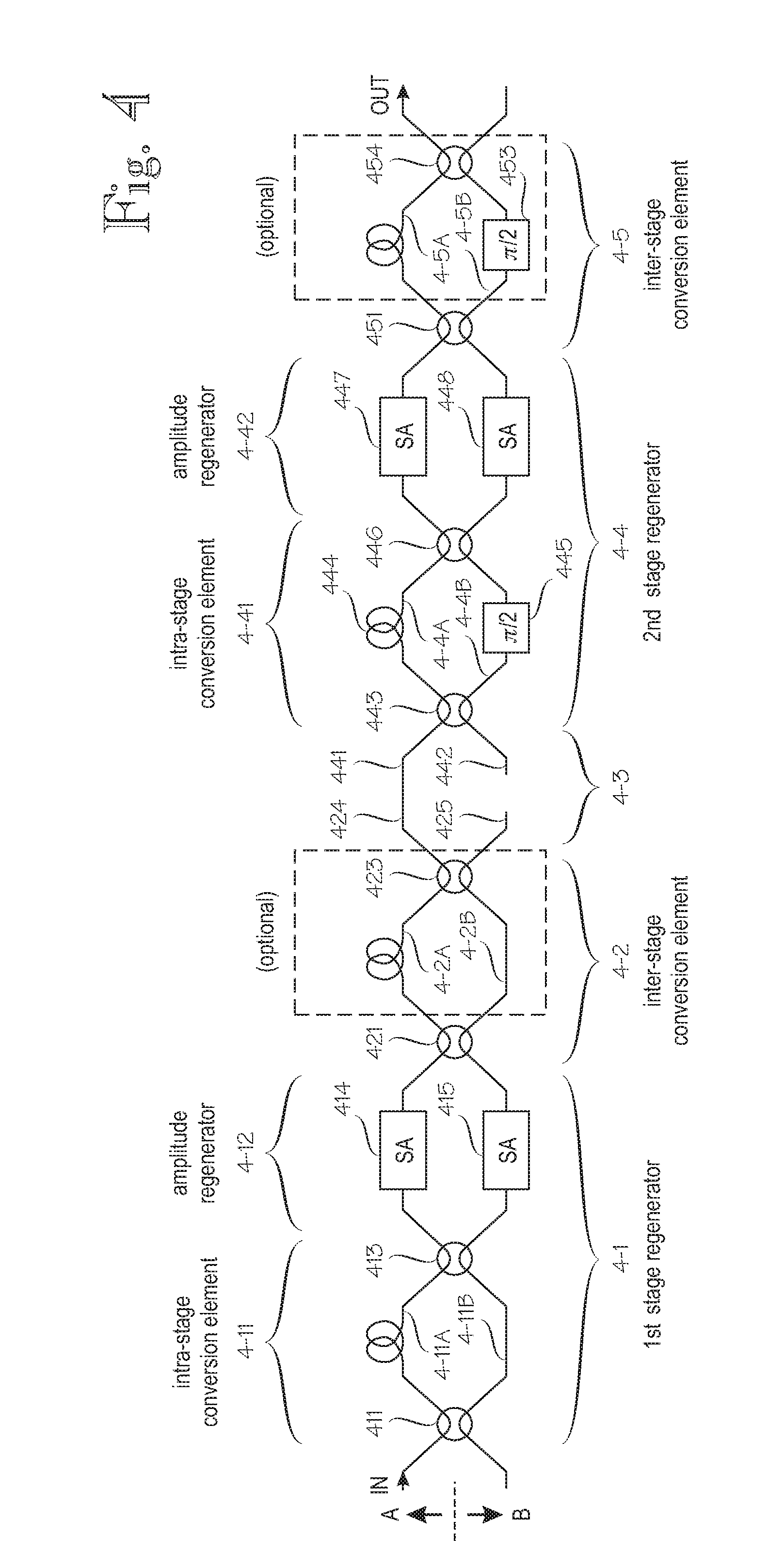
[0067]FIG. 4 shows an embodiment for QPSK or DQPSK operation, wherein a first-stage regenerator 4-1 and a second stage regenerator 4-4 are coupled in a cascade arrangement such that the two regenerators regenerate symbol pairs with different nominal phase differences. Reference signs A and B generally denote the two signal arms of the arrangement. In the present embodiment, section or block 4-11 is a conversion element internal to the first stage regenerator, called herein an intra-stage conversion element. In the present embodiment it is implemented by means of a first delay interferometer, which comprises a first 3 dB coupler 411, a first optical path 4-11A, a second optical path 4-11B, and a second 3 dB coupler 413. The two optical paths 4-11A and 4-11B differ in optical path length by an amount which corresponds to a difference of one symbol period, as discussed above. As is known to those skilled in the art, structures involving interferometers are normally implemented such tha...


PUM


Abstract

An optical signal regeneration technique includes receiving optical symbols in a phase-modulation format. The received symbols are converted to symbols in a phase/amplitude-modulation format. A first amplitude regeneration, which involves reduction of amplitude noise, is applied to a first symbol pair. A modulation format conversion is performed on the optical signal in the phase/amplitude modulation format after the first amplitude regeneration. A second amplitude regeneration is applied to a second symbol pair, wherein the first and second symbol pairs differ from one another in respect of at least one different feature, which is selected from a group that includes a different nominal phase value assigned to the symbols of the symbol pair and a different temporal distance between the symbols of a symbol pair.

Description

RELATED APPLICATION DATA[0001]The present application is a continuation of a U.S. provisional application Ser. No. 61 / 150,396, filed 6 Feb. 2009.FIELD OF THE INVENTION[0002]The invention relates to regeneration of optically transmitted signals and particularly to regeneration of optically transmitted telecommunication signals encoded in BPSK (binary phase-shift keyed and QPSK (quaternary phase-shift keying) modulation formats as well as in variations of these formats, such as DPSK (differential phase-shift keying) and DQPSK (differential quaternary phase-shift keying).BACKGROUND OF THE INVENTION[0003]In QPSK modulation, which is used as an illustrative but non-restrictive example for describing the invention, signal is transmitted in bit pairs. In other words, one symbol contains two bits of information. The four possible bit pairs are encoded into four different phase values, which can be absolute phase values or relative phase differences between two consecutive symbols. This is i...

Claims


Application Information

Patent Timeline
IPC IPC(8): H04B10/00
CPCH04B10/677
Inventor VON LERBER, TUOMOMATTILA, MARCOTERVONEN, ARIWEIERSHAUSEN, WERNER
Owner LUXDYNE
Why Eureka
Try Eureka