Solid oxide fuel cell systems with hot zones having improved reactant distribution

a fuel cell and hot zone technology, applied in the field of solid oxide fuel cell systems with hot zones, can solve the problems of high cost components, labor intensive and extremely difficult to automate process, and negating power consumption most practical benefits in many applications

Active Publication Date: 2010-08-12
SILICON VALLEY BANK +1
View PDF3 Cites 37 Cited by
  • Summary
  • Abstract
  • Description
  • Claims
  • Application Information

AI Technical Summary

Benefits of technology

[0019]It is still another object of the subject technology to locate the CPOX reactor at a boundary of, partially outside or even outside of the hot zone to reduce or control preheating and enable liquid fuel feed. Preferably, the feed end of the CPOX reactor is easily accessed and not obstructed by other hot zone structures.
[0022]It is yet another object of the subject technology to provide uniform air flow on the cathode side in the radial directions while minimizing regions of stagnant air. One embodiment uses a central feed tube.
[0023]It is still another object of the subject technology to increase thermal recuperation effectiveness by using counter-flow heat exchanger designs.
[0027]In still another embodiment, the solid oxide fuel cell system further includes an exhaust end tube sheet with an exhaust can depending therefrom. A sheath scalingly surrounds the feed tube and sealingly couples to the exhaust end tube sheet so that an anode exhaust plenum is formed at the lower end of the stack within the exhaust can. As a result, detrimental homogenous combustion will not occur at the bottom of the stack and a reducing environment is maintained about the electrical interconnects. Further, in the event that the system were laid on its side, the sheath and, thereby, the exhaust end tube sheet would carry some of the load of the stack to help prevent damage.

Problems solved by technology

In some instances, an external furnace could provide a hot environment but the furnace size, weight, and power consumption may negate most practical benefits in many applications.
This plumbing requires a high temperature sealing method such as brazing or welding, a very labor intensive and extremely difficult to automate process.
These special features are typically machined, and result in high cost components.
Further, some stack components are ceramic, and sealing metal-to-ceramic joints is difficult such as shown in U.S. Patent Application Publication No. 2004 / 0195782 published on Oct. 7, 2004.
Assembling and joining these components in close proximity is difficult and requires packing a large volume in a small space.
Consequently, the support components can undesirably occupy as much hot zone volume as the electrochemical stack 120.
The inability to closely integrate the hot zone components leads to a low hot zone power density and uneven distribution of heat.
Further, the large insulation surface around the hot zone 112 may increase heat loss.
Combustion of unutilized fuel in the stack exhaust may also occur in the hot zone.
However, the heat exchanger design of Sammes has little surface area, which leads to poor performance.
Also the Sammes system is thermally unbalanced not only axially but radial temperature variation is also significant with regions of stagnant air.

Method used


Image

  • Solid oxide fuel cell systems with hot zones having improved reactant distribution
  • Solid oxide fuel cell systems with hot zones having improved reactant distribution
  • Solid oxide fuel cell systems with hot zones having improved reactant distribution

Examples


Embodiment Construction

[0036]The present invention overcomes many of the prior art problems associated with hot zone integration in fuel cell systems. The advantages, and other features of the systems and methods disclosed herein, will become more readily apparent to those having ordinary skill in the art from the following detailed description of certain preferred embodiments taken in conjunction with the drawings which set forth representative embodiments. All relative descriptions herein such as inner, outer, upward, downward, top, bottom, left, right, up, and down are with reference to the Figures, and not meant ill a limiting sense.

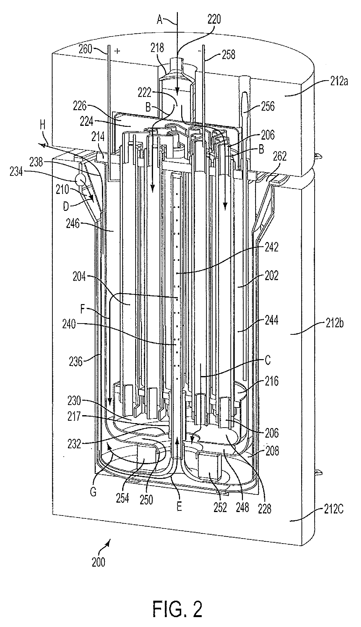
[0037]Referring now to FIG. 2, a cross-sectional view of a SOFC system 200 constructed in accordance with the subject technology is shown. The SOFC system 200 includes an elongated stack 202 that consists of a bundle of tubes or tubular cells 204. The tubular cells 204 are connected by interconnects 206 in accordance with the technology disclosed in co-pending, co-owned U....


PUM

PropertyMeasurementUnit
temperaturesaaaaaaaaaa
temperatureaaaaaaaaaa

Abstract

A Solid Oxide Fuel Cell (SOFC) system having a hot zone with a center cathode air feed tube for improved reactant distribution, a CPOX reactor attached at the anode feed end of the hot zone with a tail gas combustor at the opposing end for more uniform heat distribution, and a counter-flow heat exchanger for efficient heat retention.

Description

STATEMENT OF GOVERNMENT INTEREST[0001]This invention was made with Government support under government contract DE-FC36-04G014318 awarded by the Department of Energy to Protonex Technology LLC. The Government may have certain rights in the invention.BACKGROUND OF THE INVENTION[0002]1. Field of the Invention[0003]The subject disclosure relates to fuel cells, and more particularly to solid oxide fuel cell systems having hot zones with improved reactant distribution, more uniform heat distribution, and / or more efficient heat retention.[0004]2. Background of the Related Art[0005]Referring to FIG. 1, a schematic view of a generator 110 with a hot zone 112 is shown. The generator 110 has an electrochemical stack or solid oxide fuel cell (SOFC) 120 typically operating at temperatures above 600° C., Several other support components are also operating at elevated temperature.[0006]Commonly, the SOFC 120 is located within a hot environment to facilitate proper operation. In some instances, an...

Claims


Application Information

Patent Timeline
Patent Type & Authority Applications(United States)
IPC IPC(8): H01M8/04H01M8/10
CPCH01M8/04089H01M8/0606H01M8/0662H01M8/243H01M8/04201Y02E60/50Y02E60/525H01M8/004H01M2008/1293H01M8/2457
Inventor POSHUSTA, JOSEPH C.BOOTEN, CHARLES W.MARTIN, JERRY L.
Owner SILICON VALLEY BANK
Why Eureka
Try Eureka