Non-invasive intracranial pressure sensor

a sensor and intracranial pressure technology, applied in the field of medical devices, can solve the problems of inconvenient use, inconvenient measurement, and inconvenient operation, and achieve the effects of reducing the accuracy of the measurement, and reducing the risk of surgery

Inactive Publication Date: 2010-08-12
NEURODX DEV
View PDF8 Cites 48 Cited by
  • Summary
  • Abstract
  • Description
  • Claims
  • Application Information

AI Technical Summary

Problems solved by technology

These techniques carry inherent surgical risks, require specialized facilities, and suffer from data quality limitations (such as measurement drift) resulting from the reactive biological interface.
In addition, brain aneurysms and hemorrhagic strokes may require monitoring of ICP.
An increase in ICP causes compression of the brain tissues, starting with the ventricular and vascular spaces, and impedance of cerebral blood flow, leading to ischemia and brain damage (Ref. 5).
In addition, brain aneurysms and hemorrhagic strokes may require monitoring of ICP.
It is probable that patient and time-dependent differences in ICP exist, making it difficult to define a universally “normal” ICP value—suggests the importance of ongoing measurements to evaluate changes and trends.
These methods are all invasive, and carry risks of hemorrhage, infection, and obstruction.
Furthermore direct contact between the probe and reactive biological tissues commonly results in sensor drift and malfunction.
These invasive methods of measuring ICP can only be performed in specialized facilities where neurosurgeons are available.
Previous attempts to measure intracranial pressure using intraocular tonometry (Ref. 21), MRI scanning algorithms (Ref. 22), acoustic emissions (Ref. 23), visual evoked potentials (Ref. 24), transcranial Doppler (Ref. 25), bioimpedance (Ref. 26), ultrasonic resonance (Ref. 27), skull pulsation (Ref. 28) and other noninvasive techniques have been hampered by expensive, cumbersome and non-portable equipment, as well as complex and unreliable software.
All of these techniques require specialized training and most have failed validation trials.

Method used


Image

  • Non-invasive intracranial pressure sensor
  • Non-invasive intracranial pressure sensor
  • Non-invasive intracranial pressure sensor

Examples


Embodiment Construction

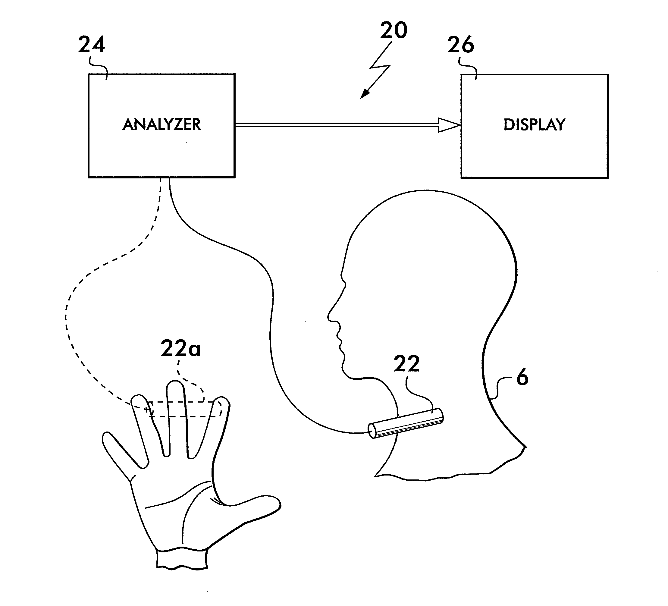
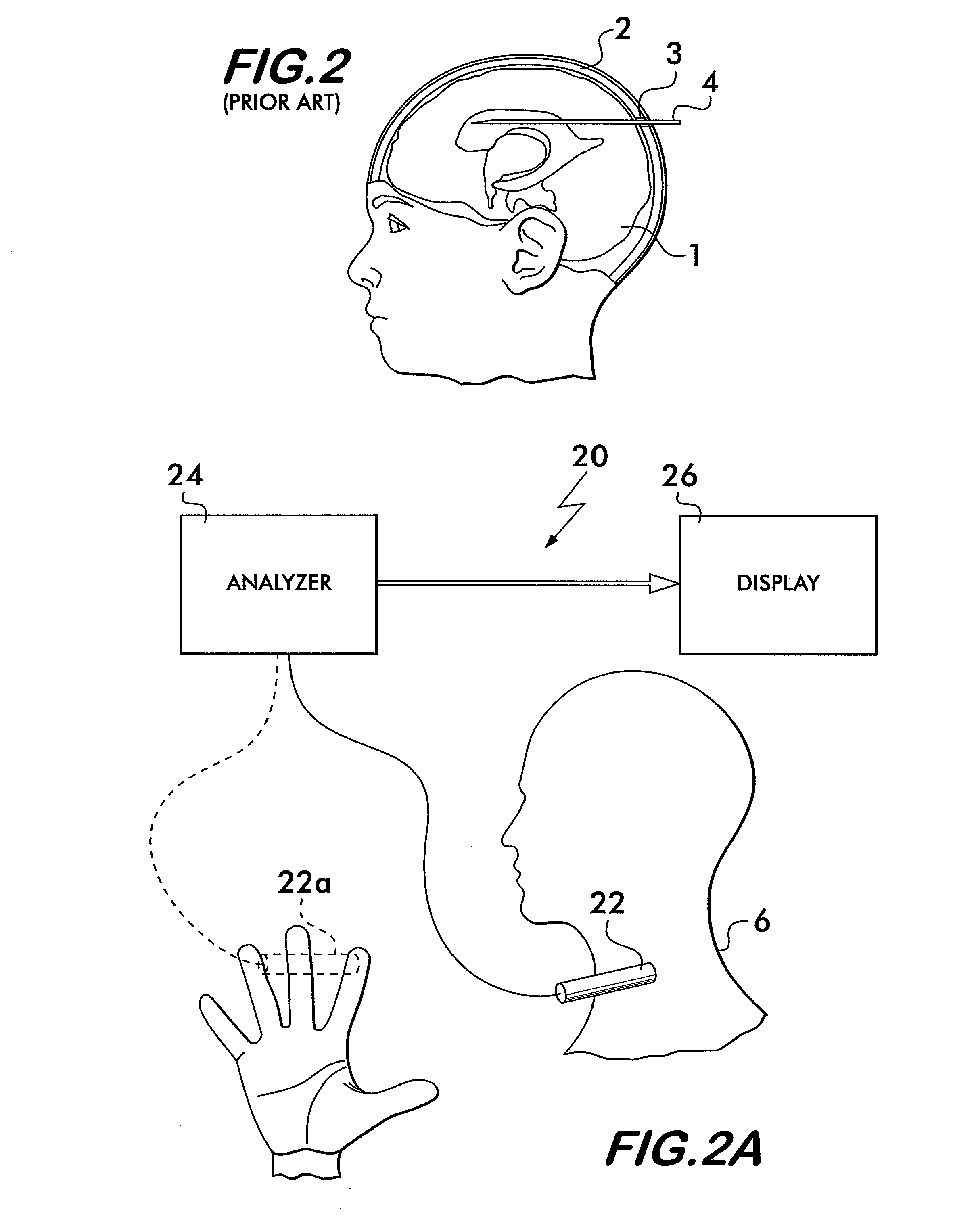
[0031]The present invention 20 is a non-invasive, hand-held device for measuring intracranial pressure (ICP). FIG. 2A depicts a block diagram of the system 20 which comprises a primary sensor 22, an analyzer 24 and an output device 26 (e.g., a monitor) for displaying the ICP and associated data. A reference sensor 22a (as will be discussed in detail later) may also be used but is not required. FIGS. 2B and 2C provide a flow diagram of the method 100 of the present invention.

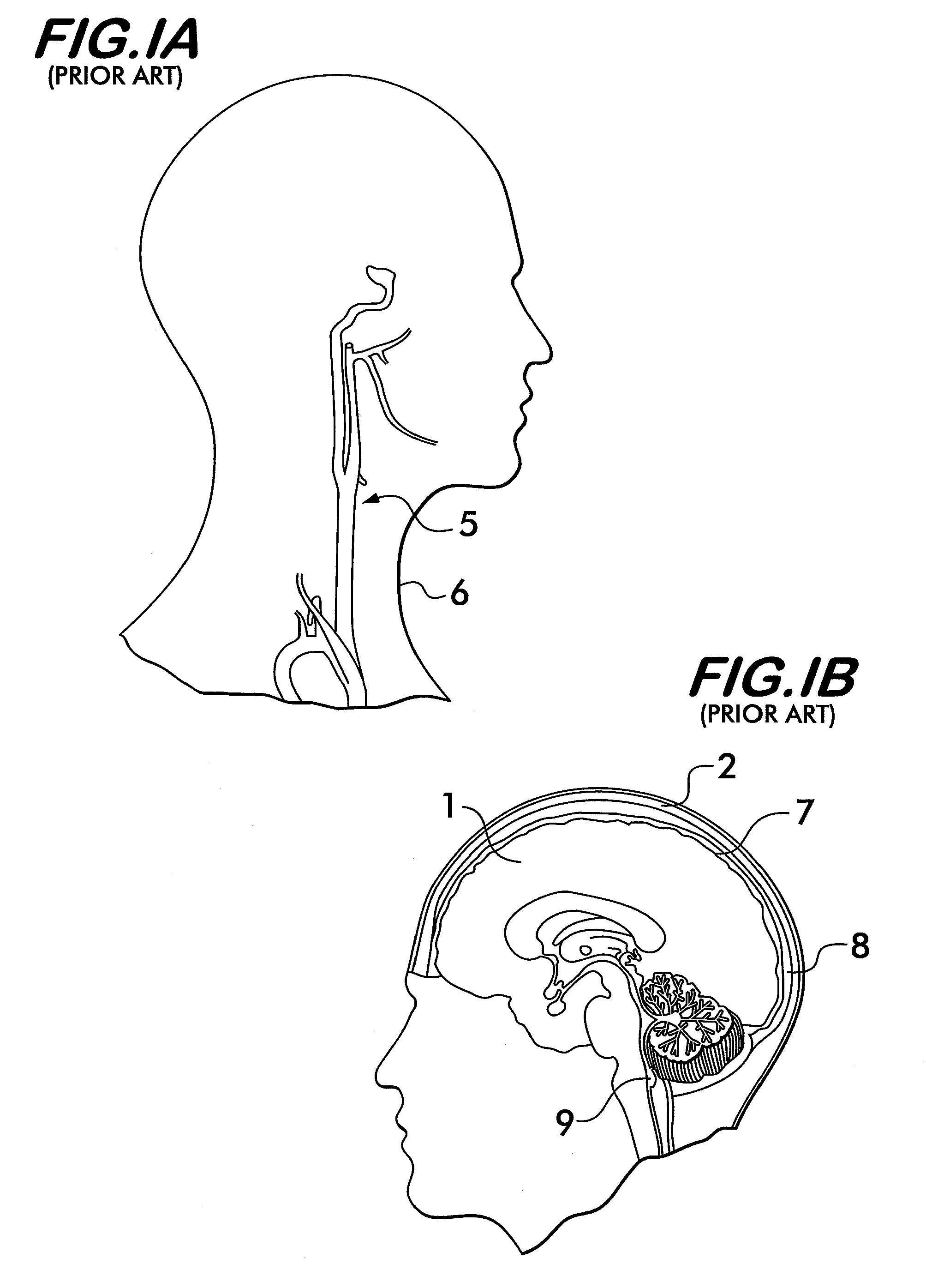
[0032]The invention 20 derives ICP from quantitative analysis of the pulse pressure waveform in the arteries supplying blood to the brain and preferably also based upon reference arteries (e.g., artery in the index finger). As explained previously, blood reaches the brain (mainly) via branches of the common carotid arteries 5 (see FIG. 1A). The carotid pressure wave is partly reflected upon striking the smaller diameter (and higher hydraulic impedance) cerebral vascular bed and this reflection contributes to the ...


PUM


Abstract

A system and method for non-invasively detecting intracranial pressure (ICP) of a living being by detecting impedance mismatches between carotid arteries and cerebral vessels via a reflection of the carotid pressure waveform using a pressure sensor positioned against the palpable carotid artery, as well as analyzing the reflection and comparing the analysis with known cerebral vasculature data, to calculate ICP non-invasively. A remote blood pressure waveform can also be used to compensate for blood system impedance.

Description

CROSS-REFERENCE TO RELATED APPLICATIONS[0001]This PCT application claims the benefit under 35 U.S.C. §119(e) of Provisional Application Ser. Nos. 60 / 953,606 filed on Aug. 2, 2007, entitled NON-INVASIVE PULSE WAVEFORM ANALYSIS FOR MEASURING INTRACRANIAL PRESSURE IN TRAUMATIC BRAIN INJURY and 61 / 059,496 filed on Jun. 6, 2008, entitled NONINVASIVE INTRACRANIAL PRESSURE MONITOR, and all of whose entire disclosures are incorporated by reference herein.BACKGROUND OF THE INVENTION[0002]1. Field of Invention[0003]The present invention generally relates to medical devices and more particularly to systems and methods for measuring intracranial pressure non-invasively.[0004]2. Description of Related Art[0005]Intracranial pressure (ICP) monitoring is a critical unmet need in the neurosurgical market. Current ICP measurement techniques require placement of a pressure probe in contact with cerebrospinal fluid (CSF). These techniques carry inherent surgical risks, require specialized facilities, a...

Claims


Application Information

Patent Timeline
Patent Type & Authority Applications(United States)
IPC IPC(8): A61B5/021
CPCA61B5/02007A61B5/021A61B5/022A61B5/031A61B5/02116
Inventor SWOBODA, MAREKHOCHMAN, MATIAS G.FRITZ, FREDERICK J.
Owner NEURODX DEV
Why Eureka
Try Eureka