Air tight access floor assembly

a technology for access floor and assembly, which is applied in the direction of floor coverings, building components, building roofs, etc., can solve the problems of leaking pressurised air, vibration sensitive components of computers and other interactive equipment may be subject to gradual diminution or failure, and may still be created an unacceptable level of nois

a technology for access floor and assembly, which is applied in the direction of floor coverings, building components, building roofs, etc., can solve the problems of leaking pressurised air, vibration sensitive components of computers and other interactive equipment may be subject to gradual diminution or failure, and may still be created an unacceptable level of nois

US20100205874A1Active Publication Date: 2010-08-19ZLATAR PETER

Image

  • Air tight access floor assembly
  • Air tight access floor assembly
  • Air tight access floor assembly

Examples


Embodiment Construction

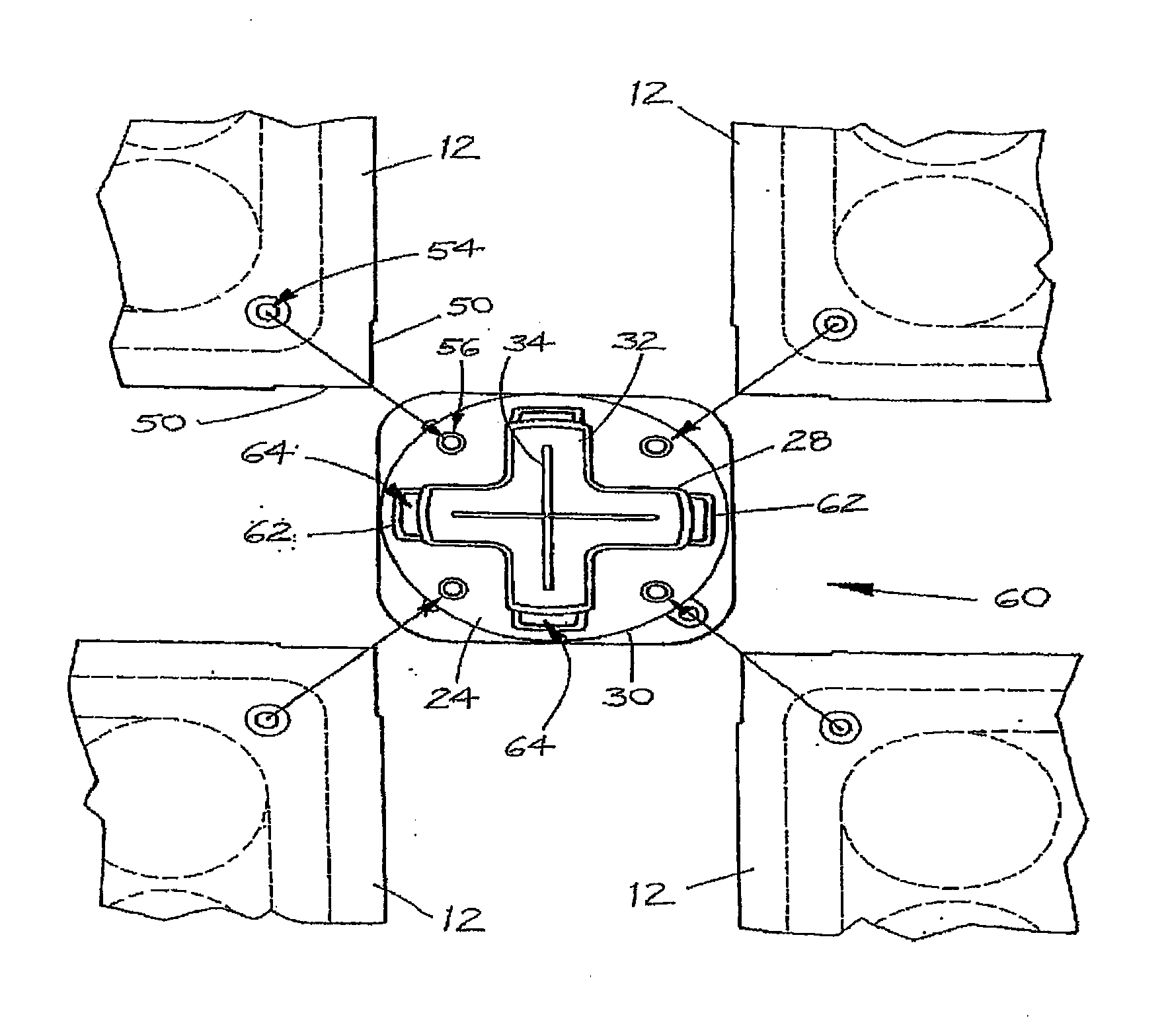
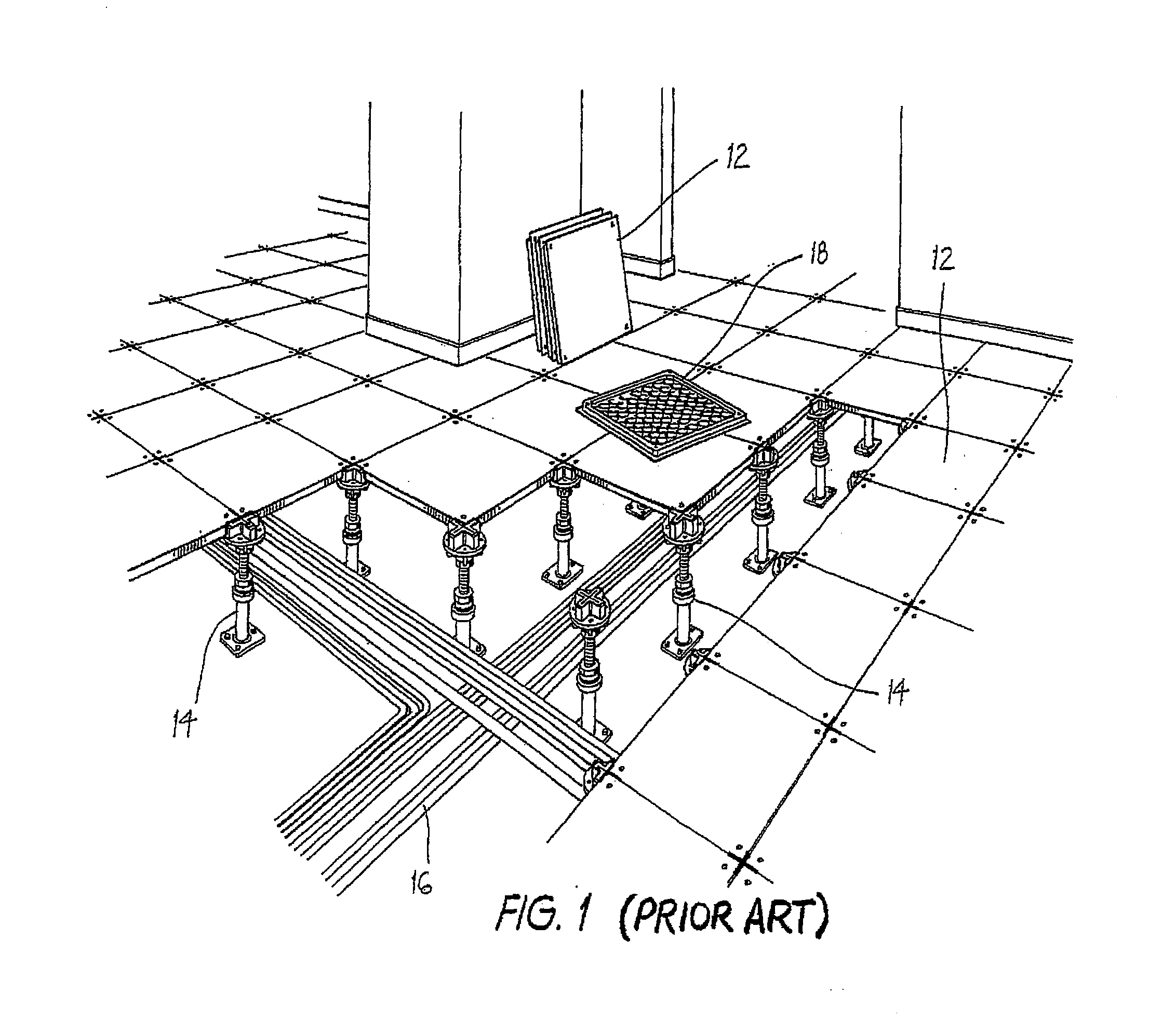
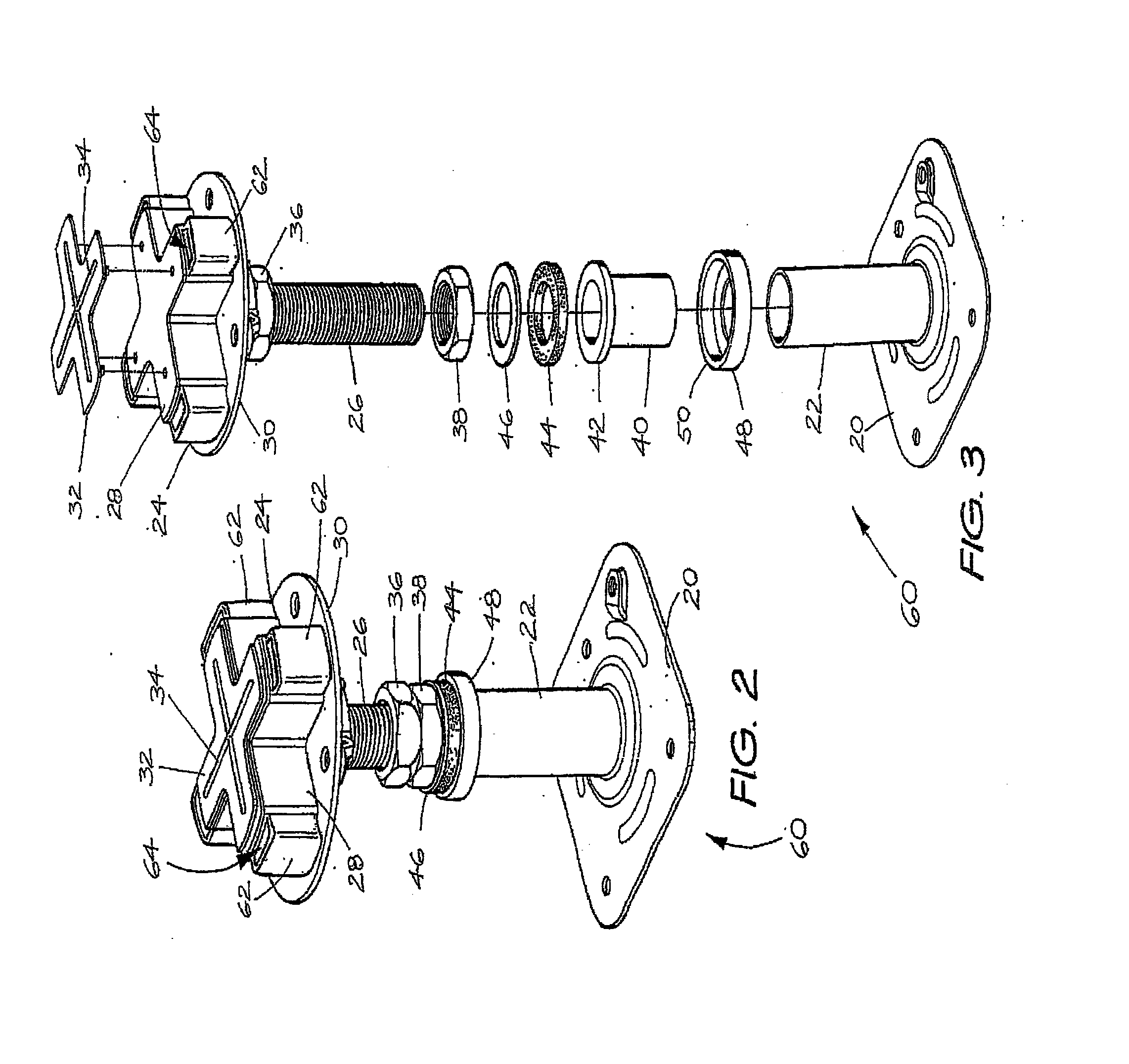
[0039]The access floor of the prior art shown in FIG. 1 has raised floor surface panels 12 supported by pedestals 14 resting upon a sub-floor, with telecommunications cabling 16 also shown in the space underlying the panels 12. The pedestals 14 are those described in the inventor's earlier Australian Patent No. 2006 200 759.

[0040]The floor panels 12 used in the access floor of the prior art are in the form of steel cementitious floor panels of 600 mm length by 600 mm width having an outer steel welded construction with an enclosed bottom pan 18 formed with a uniform pattern of generally hemispherical pockets. The cementitious material that fills the welded steel jacket of each panel 12 is lightweight and has some degree of noise attenuation properties.

[0041]The floor panels, to which reference will hereinafter be made for the purpose of describing the preferred embodiment of the present invention, are structurally identical to the floor panels 12, and will also be numbered identical...


PUM


Abstract

An air tight panel support assembly for an access floor having a plurality of panels (12) includes a pedestal (60) for supporting at least one panel of the access floor, and a stringer (66) supported by the pedestal. In use, the stringer (66) extends from one pedestal to another pedestal and supports the underside edges of adjacent panels (12) so as to close any gap therebetween.

Description

FIELD OF INVENTION[0001]The present invention relates to access flooring and, in particular, to an air tight panel support assembly for an access floor.BACKGROUND OF INVENTION[0002]Access flooring is a common feature of many computer, media and communication rooms. Being raised above a concrete slab or other sub-floor by pedestals, access flooring provides underlying space to conceal and arrange cabling and other service items used to operate the computers or other interactive equipment located within the room. The space beneath access flooring also allows air to distribute therethrough in a manner that can be controlled, say, by underfloor air conditioning systems, thus assisting to control the temperature of the room. Access flooring also provides some degree of noise attenuation and vibration dampening properties desirable in an office environment.[0003]The interconnecting panels which define the surface of an access floor are designed to be readily taken up and rearranged, upon ...

Claims


Application Information

Patent Timeline
19 Aug 2010
Publication
US20100205874A1
IPC
E04B5/43; E04F15/024
CPC
E04B5/43; E04F15/02452; E04F15/02429
Inventors
ZLATAR, PETAR