Exhaust system for gas turbine

a gas turbine and exhaust system technology, applied in the direction of power plant arrangement/mounting, climate sustainability, propulsive elements, etc., can solve the problems of increasing maintenance costs, reducing the life of the exhaust system, and being relatively high

Inactive Publication Date: 2010-08-19
SAFRAN NACELLES
View PDF8 Cites 46 Cited by
  • Summary
  • Abstract
  • Description
  • Claims
  • Application Information

AI Technical Summary

Benefits of technology

[0007]An object of the present invention is to propose a novel design for a by-pass gas turbine exhaust system delivering separate streams,...

Problems solved by technology

That type of design for an exhaust system presents the drawback of subjecting the primary nozzle to high mechanical loads, thereby reducing its lifetime and increasing expensive maintenance costs.
Fu...

Method used


Image

  • Exhaust system for gas turbine
  • Exhaust system for gas turbine
  • Exhaust system for gas turbine

Examples


Embodiment Construction

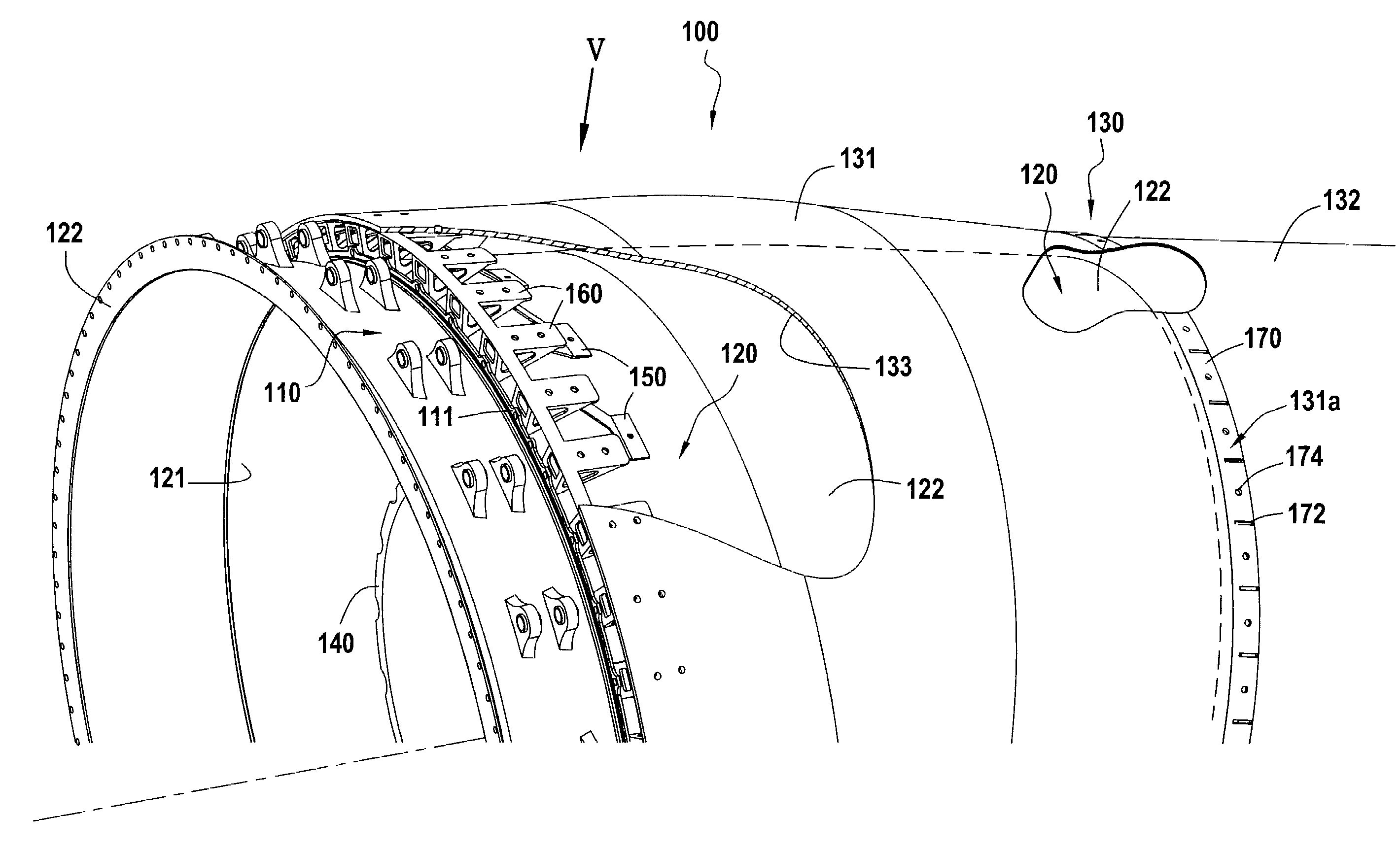
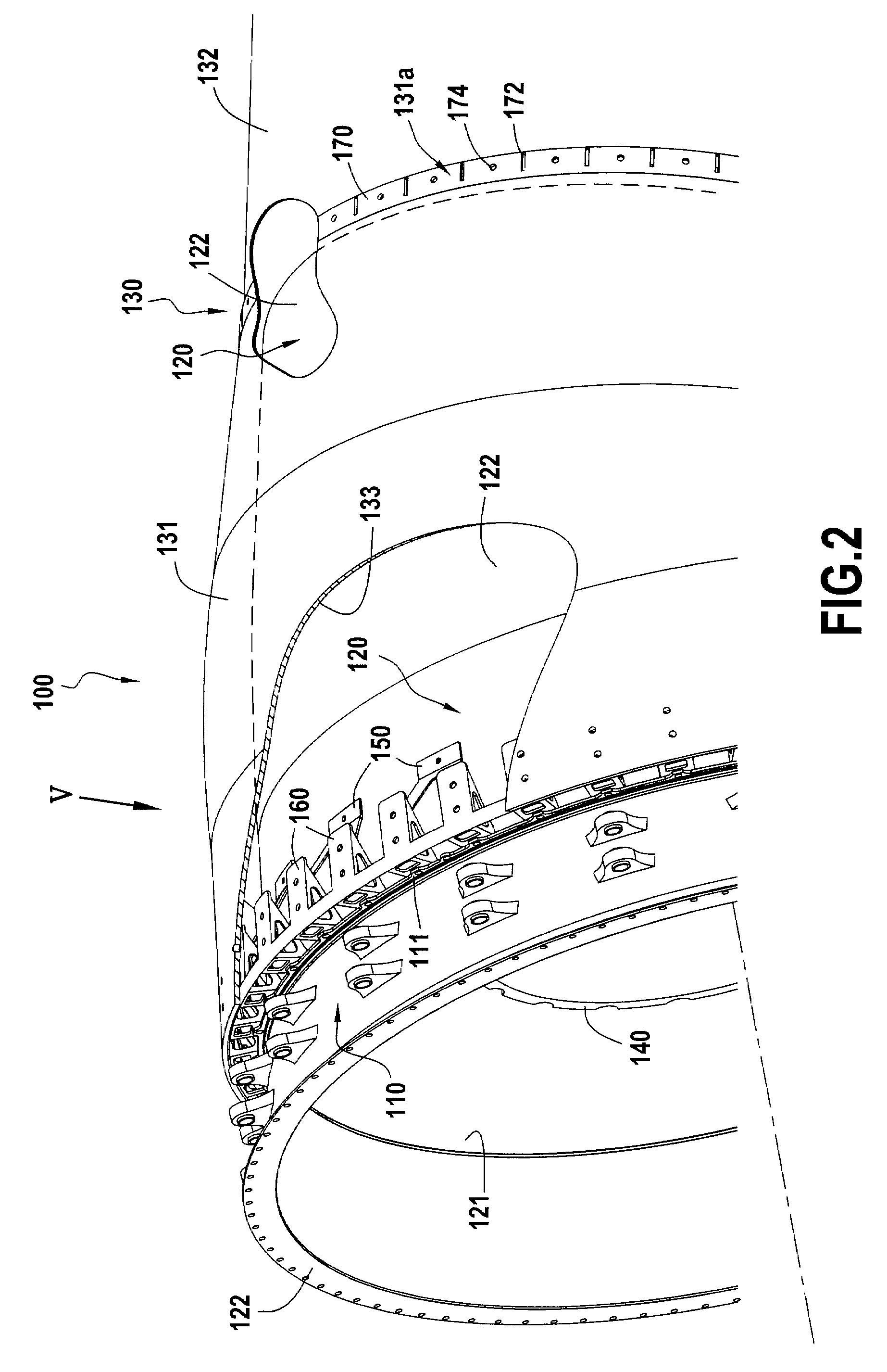
[0033]A particular but non-exclusive field of application of the invention is that of by-pass gas turbines for aeroengines. FIG. 2 shows an exhaust system 100 for a by-pass aviation gas turbine in accordance with an embodiment of the invention. The exhaust system comprises an exhaust casing 110 designed to be fastened to the outlet from the gas turbine upstream from its combustion chamber (not shown).

[0034]The exhaust system also includes a nozzle for channeling the stream from the gas turbine, which nozzle is located downstream from the exhaust casing 110 and comprises a primary nozzle 120 and a secondary nozzle 130, the secondary nozzle being made up of an upstream wall portion or upstream secondary nozzle 131 and a downstream wall portion or downstream secondary nozzle 132 that extends the primary nozzle 120 and the upstream secondary nozzle 131 in a downstream direction.

[0035]Between its inner wall 121 and a central body and an element or “plug”140 disposed therein, the primary ...


PUM

PropertyMeasurementUnit
Flexibilityaaaaaaaaaa

Abstract

The invention relates to an exhaust system (100) for channeling the streams from a by-pass gas turbine, the system comprising a stream channeling nozzle and an exhaust casing (110) for connecting the channeling nozzle to the outlet of the gas turbine, said channeling nozzle comprising a primary nozzle (120) fastened to the exhaust casing (110) and a secondary nozzle (130) placed around the primary nozzle. The exhaust system further comprises means for fastening the secondary nozzle (130) directly to the exhaust casing (110), said secondary nozzle being supported by the exhaust casing independently of the primary nozzle (120).

Description

BACKGROUND OF THE INVENTION[0001]The present invention relates to the general field of systems used for exhausting gas from a gas turbine, in particular for aviation by-pass gas turbines, i.e. gas turbines having at least two distinct streams flowing therethrough (a primary or “core” stream and a secondary or “by-pass” stream). The invention relates more particularly to exhaust systems for such gas turbines having a primary nozzle and a secondary nozzle that are designed to be placed concentrically at the outlet from such a gas turbine.[0002]FIG. 1 is a fragmentary and diagrammatic view of an exhaust system for an aeroengine delivering separate streams and comprising a primary nozzle 10 placed inside a secondary nozzle 20 made up of two portions, namely an upstream secondary nozzle 21 and a downstream secondary nozzle 22 (where the terms “upstream” and “downstream” are used herein relative to the flow direction of the stream of gas through the engine). A central body or “plug”30 is ...

Claims


Application Information

Patent Timeline
IPC IPC(8): F02K1/40B23P11/00
CPCF02K1/04Y10T29/4932F02K1/78F02K1/80F05B2260/301Y02T50/672F05D2240/128F05D2260/30F05D2300/702F05D2300/2261F05D2300/224F05D2300/603F05D2300/614F05D2300/226Y10T29/49323F02K1/52F01D25/30Y02T50/60
Inventor CONETE, ERICBAROUMES, LAURENTHABAROU, GEORGES
Owner SAFRAN NACELLES
Why Eureka
Try Eureka