Welding solid wire

a solid wire and iron base technology, applied in the direction of welding/cutting media/materials, welding apparatus, manufacturing tools, etc., can solve the problems of high heat treatment cost, insufficient low-temperature toughness, and inability to ensure stable low-temperature toughness in the as-welded state, etc., to achieve high crack initiation resistance, high absorption energy, and high low-temperature toughness.

Active Publication Date: 2010-08-19
KOBE STEEL LTD
View PDF3 Cites 16 Cited by
  • Summary
  • Abstract
  • Description
  • Claims
  • Application Information

AI Technical Summary

Benefits of technology

[0018]In accordance with the present invention, it becomes possible to provide a similar composition metal type welding solid wire capable of forming a welded joint part with cryogenic characteristics generally equivalent to those of the base metal upon welding a cryogenic steel typified by a 9% nickel steel. Particularly, by the welding solid wire of the present invention, it is possible to obtain a welded joint part holding a sufficient low-temperature toughness resulting in a high absorption energy by the Charpy impact test, and in addition, having a very high level in the measured value of the crack initiation resistance by the instrumented Charpy impact testing method. As a result of this, it is possible to form a welded joint part having excellent cryogenic characteristics appropriate to the brittle fracture phenomenon of an actual large-size welded structure.
[0019]Thus, by use of such a similar composition metal type welding solid wire of the present invention, it is possible not only to more reduce the cost of the wire itself than with a high alloy type wire, but also to clear a large economical burden due to an increase in plate thickness of the base metal steel associated with the insufficient strength of the welded joint. Further, it is also possible to resolve the problems in quality such as reduction of the thermal cracking resistance of the same welded joint part and the deterioration of the thermal fatigue characteristics due to a difference in thermal expansion coefficient. This promotes manufacturing of a welded structure including a cryogenic steel. This further enables remarkable enhancement of popularization in various applications of the cryogenic steel having excellent characteristics.

Problems solved by technology

From such background, up to now, various studies have been also made on a welding technology of a cryogenic steel, leaving many insufficient aspects from the standpoint of satisfying both the cost effectiveness and the cryogenic characteristics.
However, with the current welding method, a stable low-temperature toughness cannot be ensured in the as-welded state.
Further, for a welded structure of a cryogenic steel, a heat treatment for recovering the toughness after completion of welding is very difficult.
Accordingly, a welding wire having components similar to those of the cryogenic steel is not practical.
As a result, despite use of a 9% nickel steel as a 70-kg / mm2 class high tensile strength steel, the strength of the welded joint part is low.
In order to ensure the strength, disadvantageously, the plate thickness of the whole welded structure must be increased.
Therefore, so long as a high nickel alloy welding wire is used, the high strength of a 9% nickel steel cannot be utilized sufficiently.
This imposes double economic burdens of an increase in plate thickness of the welded structure and an increase in quantity of an expensive high nickel alloy welding wire consumed.
Further, with welding by a high nickel alloy, a problem of high temperature cracking inherently occurs.
In addition, a large difference in components from a 9% nickel steel, which is the base metal, also creates a problem of thermal fatigue due to a difference in thermal expansion coefficient, or the like.
In spite of this, in actuality, the scope of application thereof is remarkably limited.
However, this method has a problem of an increase in number of steps in executing welding.
This method is limited to the improvement of the partial low-temperature toughness of only the final welded layer in the welded joint part to the end.
Therefore, unfavorably, this method inherently has a problem of having a limit in improving the low-temperature toughness of the whole weld metal controlling the characteristics of the welded joint.
This entails an increase in number of steps, and further an increase in cost.
Further, the study on the wire components is insufficient.

Method used


Image

  • Welding solid wire
  • Welding solid wire

Examples


embodiments

Embodiment 1 (Experimental Example of REM Addition)

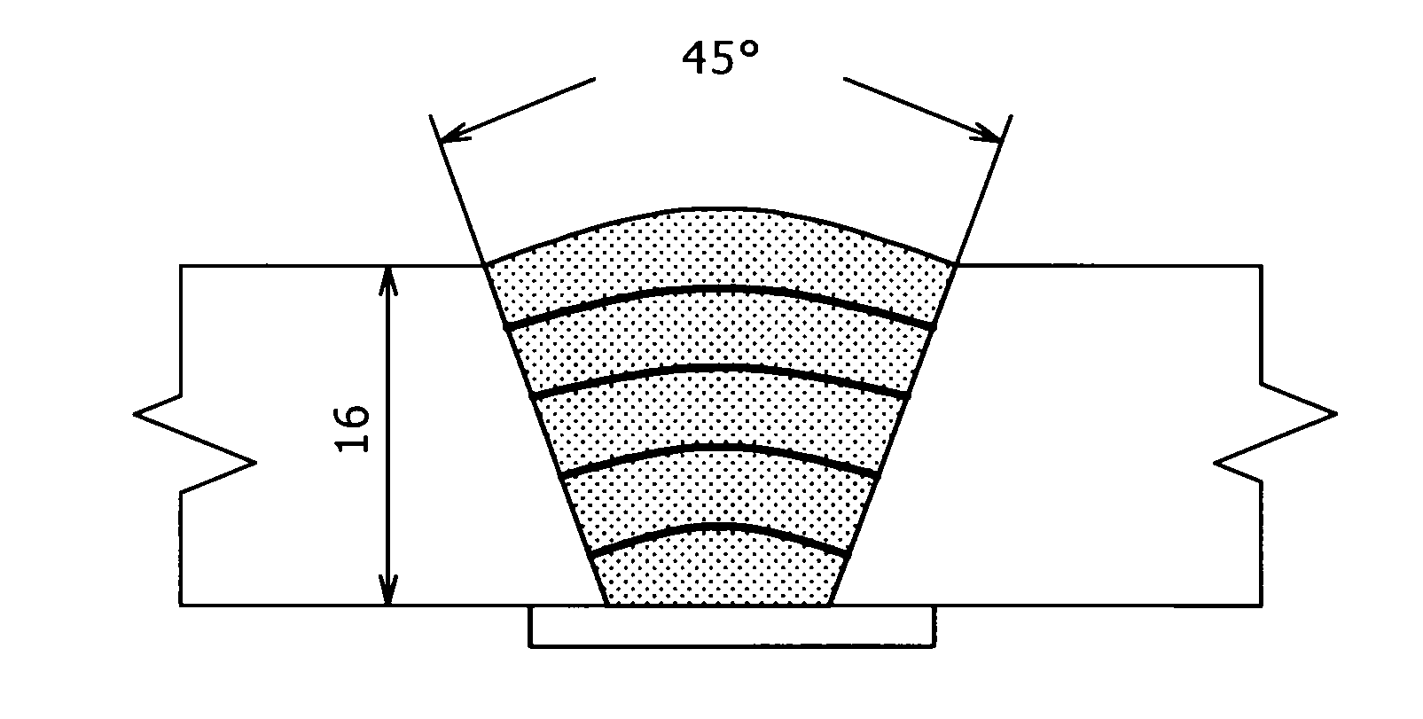
[0048]Using a 9% nickel steel base metal (plate thickness: 16 mm) including chemical components (mass % except for O=oxygen, balance: iron) shown in Table 1, processing of a groove in the shape shown in FIG. 1 was performed. Then, using each welding wire including chemical components (mass % except for O=oxygen, balance: iron and inevitable impurities) shown in Table 2, TIG welding was performed under the conditions A or B shown in Table 3. Incidentally, for welding, a fully automatic TIG welding apparatus equipped with an automatic arc control device was used. Welding was performed in the flat position.

TABLE 1CSiMnNiPSO0.050.290.389.10.0050.00420 ppm

TABLE 2WireNo.CSiMnPSNiTiREMOAlB1′0.050.110.700.0030.00313.0——50 ppm0.002—2′0.060.130.650.0040.00510.5 0.008—85 ppm0.004—3′0.030.090.730.0060.00310.90.03—70 ppm0.020—4′0.090.140.750.0040.00213.70.12—60 ppm0.027—5′0.040.080.650.0020.00310.6— 0.00475 ppm0.048—6′0.040.110.240.0080.00410.7...

embodiment 2 (

Experimental Example of Chromium Addition)

[0054]Using a 9% nickel steel base metal (plate thickness: 16 mm) including chemical components (mass % except for O=oxygen, balance: iron) shown in Table 5, processing of a groove in the shape shown in FIG. 1 was performed in the same manner as in Embodiment 1. Then, using each welding wire including chemical components (mass % except for O=oxygen, balance: iron) shown in Table 6, TIG welding was performed under the conditions A or B shown in Table 3 in the same manner as in Embodiment 1. Incidentally, for welding, a fully automatic TIG welding apparatus equipped with an automatic arc control device was used. Welding was performed in the flat position.

TABLE 5CSiMnNiPSO0.060.350.418.90.0040.00525 ppm

TABLE 6WireNo.CSiMnPSNiCrOAlB1′0.040.120.550.0040.00212.0—60 ppm0.0060.0022′0.030.090.480.0030.00611.81.950 ppm0.003—3′0.040.070.760.0060.00410.14.743 ppm0.026—4′0.090.120.700.0060.00413.75.3140 ppm 0.0380.002

[0055]After completion of welding, in...


PUM

PropertyMeasurementUnit
thicknessaaaaaaaaaa
temperatureaaaaaaaaaa
absorption energyaaaaaaaaaa

Abstract

It is an object of the present invention to provide a similar composition metal type welding solid wire capable of forming a welded joint having excellent cryogenic characteristics, such as ensuring a low-temperature toughness equivalent to that of the cryogenic base metal, and in addition, further having a high crack initiation resistance, and a weld metal thereof. The welding solid wire of the present invention is an iron base welding solid wire including carbon: 0.10 mass % or less (not inclusive of 0%), silicon: 0.15 mass % or less (not inclusive of 0%), nickel: 8.0 to 15.0 mass %, manganese: 0.10 to 0.80 mass %, and Al: 0.1 mass % or less (not inclusive of 0%), and oxygen in an amount of 150 ppm or less (inclusive of 0), characterized by including: a REM: 0.005 to 0.040 mass %, or chromium: 4.0 mass % or less (not inclusive of 0%).

Description

TECHNICAL FIELD[0001]The present invention relates to an iron base welding solid wire suitable for welding of cryogenic steels including a 9% nickel steel, and a weld metal thereof. More particularly, the present invention relates to a similar composition metal type solid wire for cryogenic steel welding which forms a welded joint part excellent in cryogenic characteristics in welding aimed at a cryogenic steel, and a welded metal thereof.BACKGROUND ART[0002]As is well known, a 9% nickel steel is a high tensile strength steel to be used at cryogenic temperatures to −196° C. or less, and has a high proof stress and an excellent low-temperature toughness. Accordingly, the 9% nickel steel has been widely used for a storage tank of LNG, liquid nitrogen, liquid oxygen, or the like, related equipment thereof, or the like. Thus, the 9% nickel steel has an excellent cryogenic toughness. However, in order to utilize this feature, as a matter of course, the welded joint part is also required ...

Claims


Application Information

Patent Timeline
Patent Type & Authority Applications(United States)
IPC IPC(8): B23K35/24
CPCB23K35/0261B23K35/3026B23K35/3033B23K35/3066C22C38/14C22C38/005C22C38/02C22C38/04C22C38/08C22C38/002
Inventor NAKO, HIDENORITAKEDA, HIROYUKIOKAZAKI, YOSHITOMISUENAGA, KAZUYUKINAKANISHI, KOHJIROH
Owner KOBE STEEL LTD
Why Eureka
Try Eureka