Laser welding method and apparatus

a laser welding and welding bead technology, applied in welding apparatus, metal-working equipment, manufacturing tools, etc., can solve problems such as deterioration of welding beads, incomplete welding, and uneven clearan

Inactive Publication Date: 2010-08-19
MAZDA MOTOR CORP
View PDF2 Cites 24 Cited by
  • Summary
  • Abstract
  • Description
  • Claims
  • Application Information

AI Technical Summary

Benefits of technology

[0007]An object of the present invention is to provide a laser welding method and apparatus which can provide the proper welding of the...

Problems solved by technology

Further, this clearance may not be uniform, so there is a concern that the molten metal of the upper metal plate would not lower to the lower metal plate beyond the above-described clearance at a position where the clearance is relatively large.
Consequently, some incomplete welding would occur.
According to the technology...

Method used


Image

  • Laser welding method and apparatus
  • Laser welding method and apparatus
  • Laser welding method and apparatus

Examples


embodiment 1

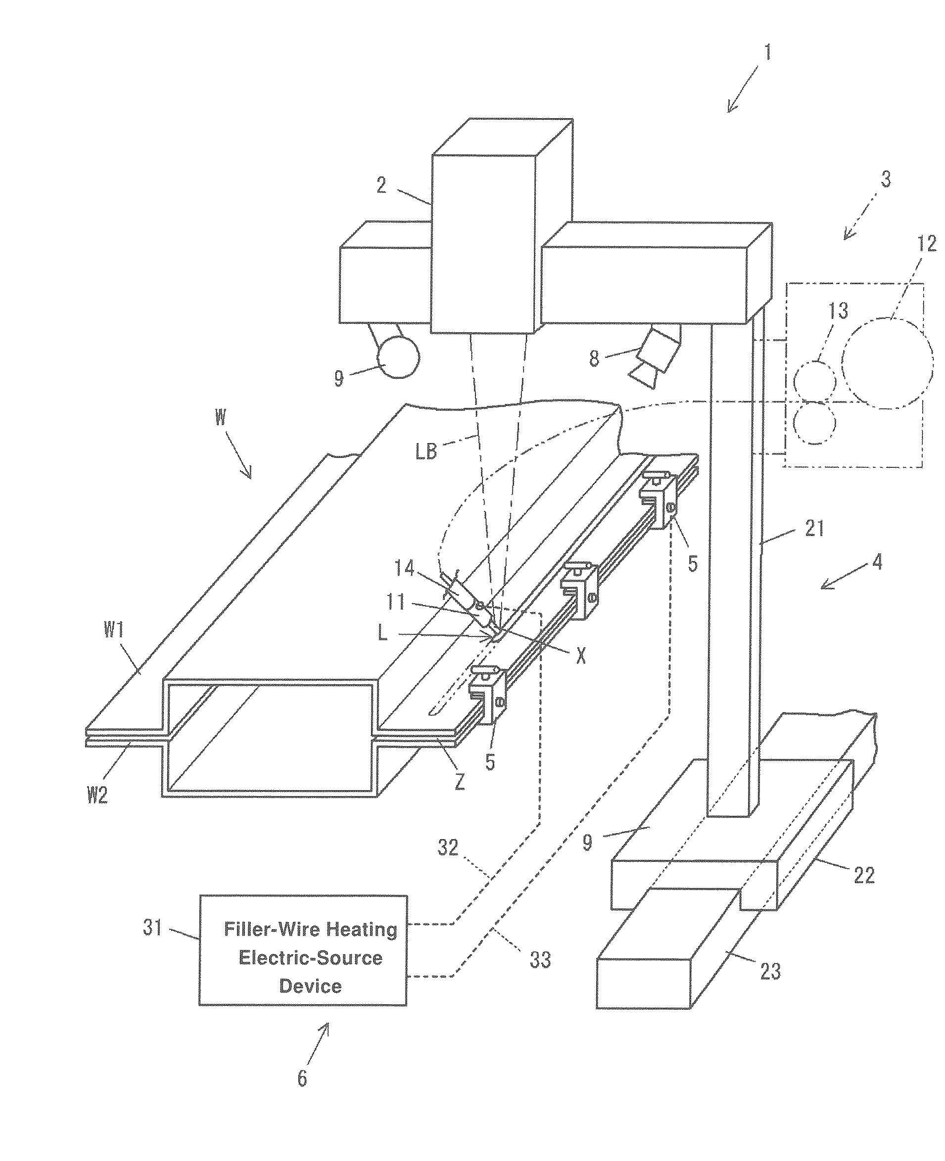
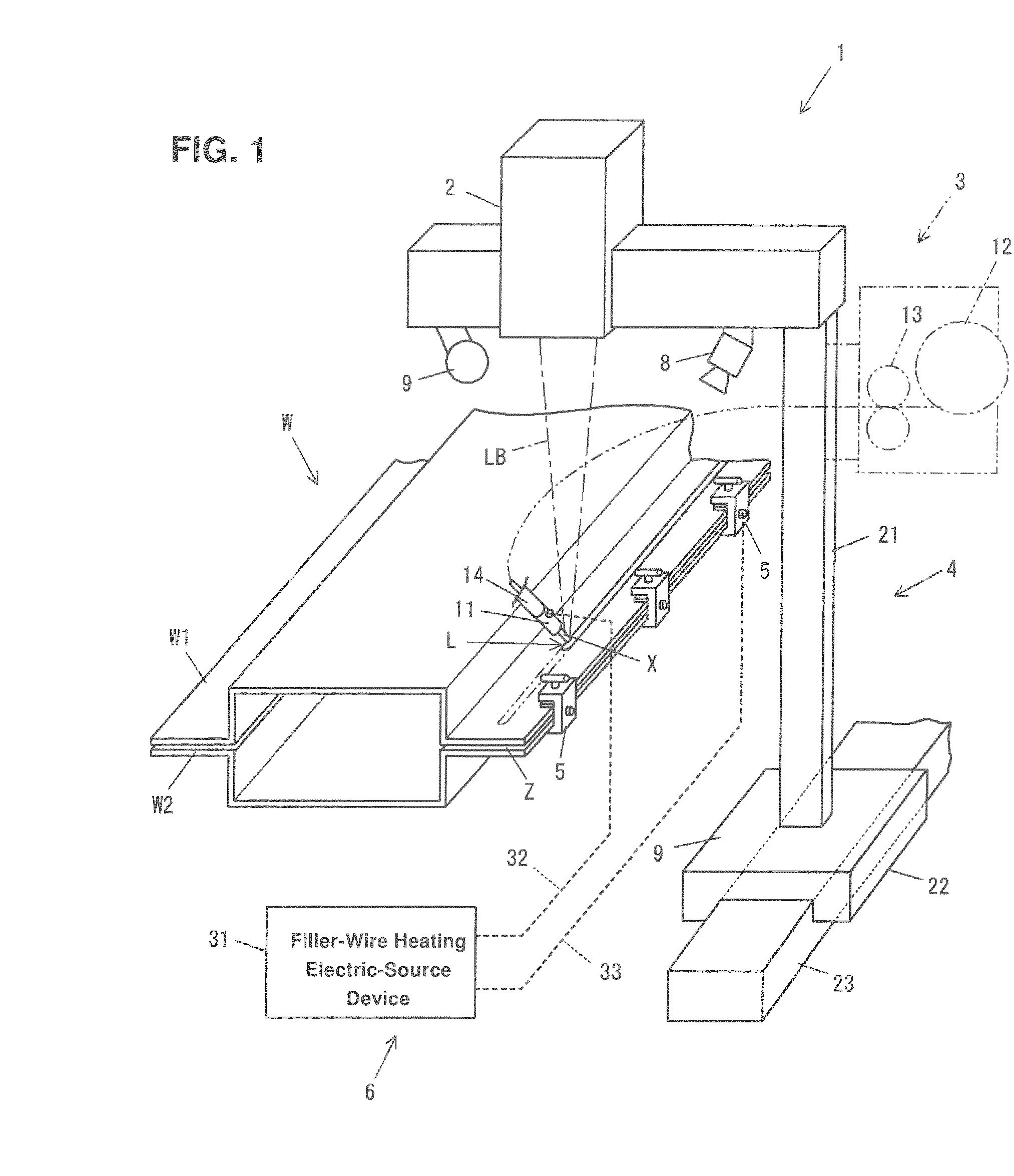
[0033]FIG. 1 is a perspective view of a laser welding apparatus 1 according to the present embodiment. The laser welding apparatus 1 comprises a laser head 2 which generates laser beams LB, a filler-wire feeding device 3 which feeds a filler wire X to a laser-beam irradiated portion L from the laser head 2, and a moving device 4 which supports the laser head 2 and the filler-wire feeding device 3 and moves them relatively to work W. Herein, the work W is comprised of upper and lower metal plates W1, W2 which have a U-shaped cross section, respectively, and flanges of which are overlapped, for example. The flanges of the metal plates W1, W2 are clamped with plural clamps 5 . . . 5, however, some clearance Z may be inevitably generated between facing faces of these metal plates W1, W2 due to their manufacturing accuracy.

[0034]The laser head 2 is constituted by using a high-power laser, such as YAG laser or carbonic-acid gas laser, and its laser power is configured to be variable. Whil...

embodiment 2

[0066]A second embodiment will be described. In the above-described first embodiment, it is determined whether or not the welding state of the upper and lower metal plates W1, W2 is proper by determining whether or not the width dy of the molten pool WY is within the range of twice through fifth times the laser-beam diameter rb. In the second embodiment, however, it is determined whether the welding state of the upper and lower metal plates W1, W2 is proper or not based on the ratio of the amount of projection hy and the width dy of the molten pool WY. Hereinafter, the present embodiment will be described referring to a flowchart of FIG. 15.

[0067]At first, the updated image data obtained by the image picking-up device 8 is inputted in step S11.

[0068]In the next step S12, the inputted image data is analyzed, and the width dy of the molten pool WY at the position which is located the specified distance da behind the laser-beam center LBc and the amount of projection hy of the molten m...

embodiment 3

[0072]A third embodiment will be described. In the third embodiment, the detecting method of the projection amount hy of the molten pool WY in the second embodiment is changed. That is, according to the present embodiment, a laser measuring device is attached to the moving device 4. This laser measuring device emits the laser beams to the molten pool WY and receives the reflected beams. Thereby, the projection amount hy of the molten pool WY is detectable. Herein, the flowchart of the present embodiment is the same as that of the above-described second embodiment. According to the third embodiment, the projection amount hy of the molten pool WY can be detected accurately, so that the accuracy of the determination of the welding state of the two metal plates W1, W2 can be improved.


PUM

PropertyMeasurementUnit
Diameteraaaaaaaaaa
Speedaaaaaaaaaa
Widthaaaaaaaaaa

Abstract

A laser welding method including a step of welding upper and lower metal plates, a step of picking up an image of a molten pool near a molten hole from the side of the upper metal plate during an execution of the welding step, a step of determining whether a welding state of the metal plates is proper or not by analyzing a generation state of the molten pool based on the image picked up in the picking-up step, and a step of adjusting at least one of a parameter of the irradiated laser beams and a feeding speed of the filler wire so that the welding state of the metal plates becomes proper in case the welding state determined in the determining step is not proper.

Description

BACKGROUND OF THE INVENTION[0001]The present invention relates to a laser welding method and apparatus of a pair of flat-plate-shaped metal plates overlapped vertically.[0002]A laser welding has been recently used as a welding method of a pair of flat-plate-shaped metal plates overlapped vertically. In the laser welding, a laser beam is irradiated toward a surface of an upper metal plate so as to move along a welding path in such a manner that a laser-beam irradiated portion of the upper and lower metal plates is molten and a line-shaped welding bead is generated.[0003]Herein, in general, the respective facing faces of the two metal plates are not flat completely, so some clearance between the metal plates is generated. Further, this clearance may not be uniform, so there is a concern that the molten metal of the upper metal plate would not lower to the lower metal plate beyond the above-described clearance at a position where the clearance is relatively large. Consequently, some in...

Claims


Application Information

Patent Timeline
IPC IPC(8): B23K26/00B23K26/21
CPCB23K26/246B23K26/03B23K26/244
Inventor TANAKA, CHIKARAKITAHARA, YOICHIRO
Owner MAZDA MOTOR CORP
Why Eureka
Try Eureka