
Gas burner boiling pot

a technology of gas burner and boiling pot, which is applied in the field of vessels, can solve the problems of inefficient use of natural gas, large loss of heat along the edge of the pot, and inability to heat up the liquid, and achieve the effect of increasing the heating performance of the liquid

Inactive Publication Date: 2010-08-19
TUNSTALL TODD BARD
View PDF10 Cites 29 Cited by
  • Summary
  • Abstract
  • Description
  • Claims
  • Application Information

AI Technical Summary

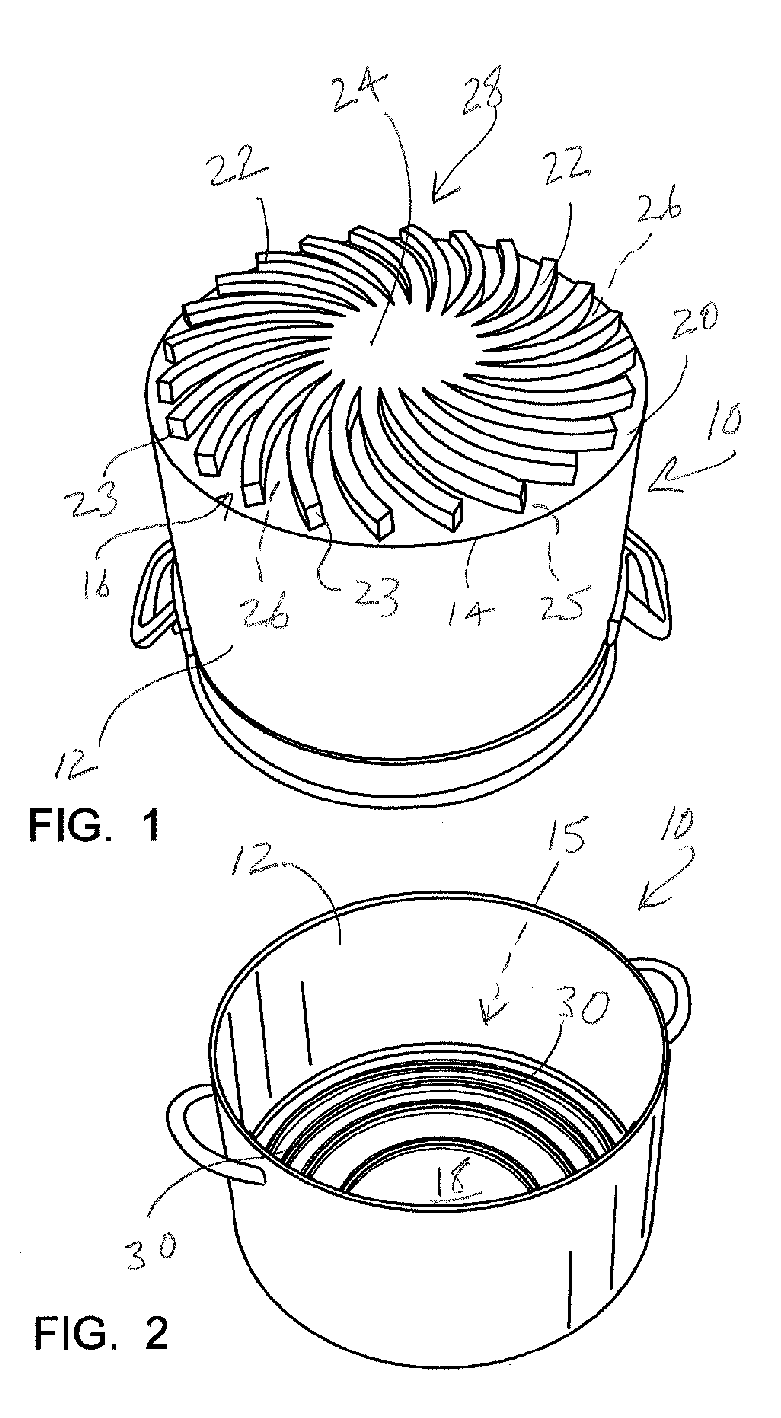
Benefits of technology

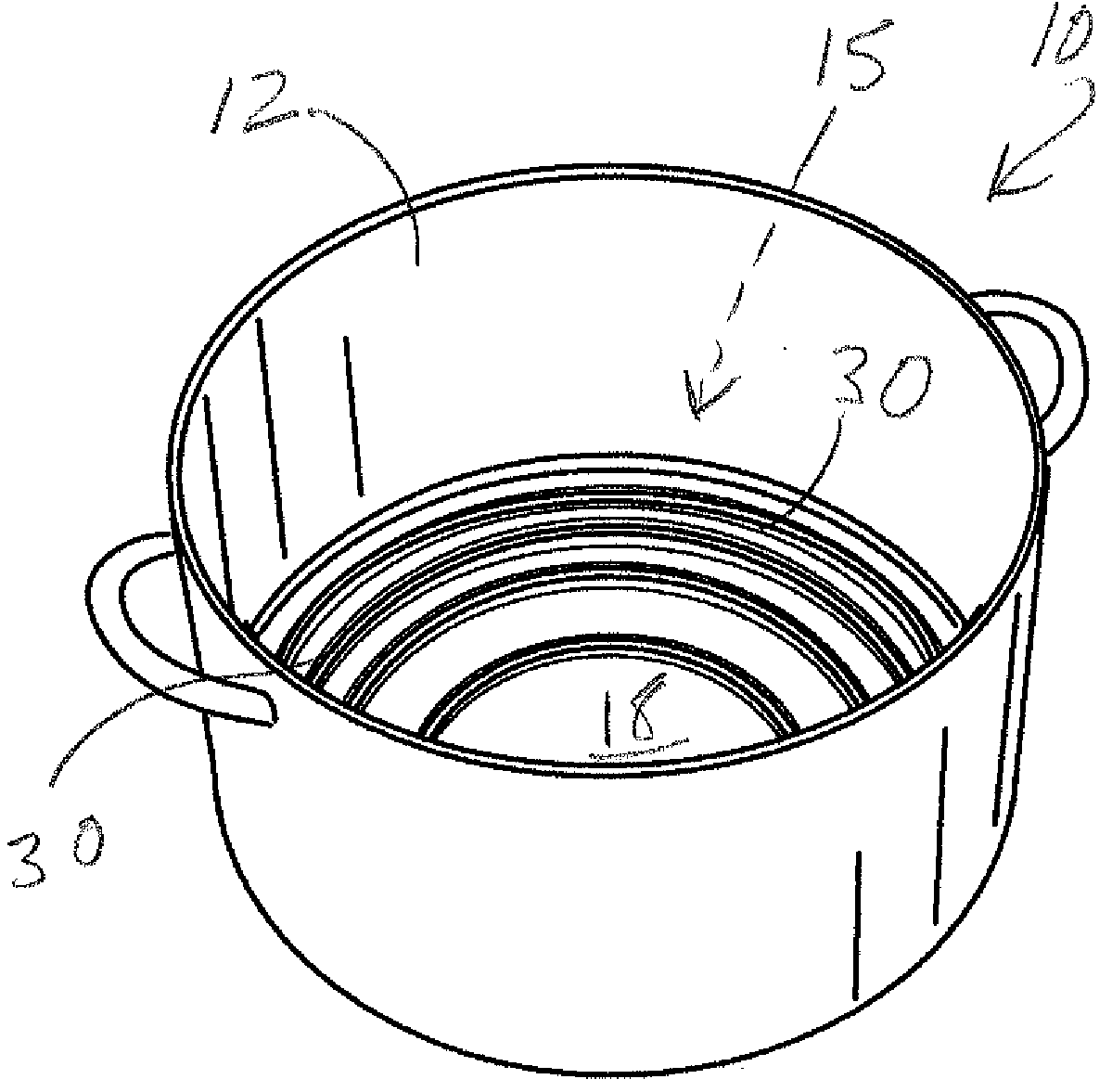
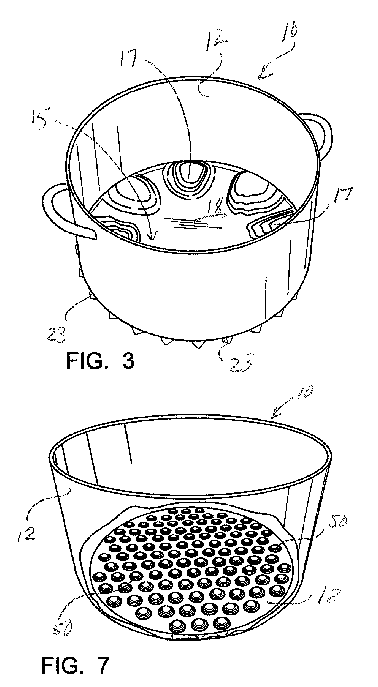
[0012]The apparatus of the present invention solves the problems in the art in a simple and straightforward matter. What is provided is a pot, having a bottom and a continuous sidewall, defining a fluid or substance containing space therein. The pot further includes a plurality of fins extending along the bottom exterior surface of the pot, in various configurations, but preferably in a series of raised, curved arms that radiate out from the center of the pot and terminate at its outer edge, defining a plurality of spaces between each radiating arm. This configuration of raised, radiating arms along the exterior bottom wall of the pot increase the surface area of the bottom of the pot and absorbs the heat from the gas burner into the pot, thereby increasing the heating performance of the liquid or substance being heated therein.
[0013]There may be further provided small mounds or waves on the interior bottom of the pot for further increasing the surface of the pot interior, which helps channel the heat in a circular motion, and helps induction of heat into the substance.
[0014]This configuration is defined as a tuned thermal sink, which is a heat exchange device which converts the energy collected from the hot gases from the burner to the liquid side of the sink (interior of the pot) with very little resistance. The ratio between the surface area on the gas side of the sink is in proportion to the liquid side of the sink making it an efficient movement of energy between the gas side and the liquid side.

Problems solved by technology

The shortcomings in this method is that although a pot placed over an open flame receives heat directly to its bottom to heat the contents of the pot, a great amount of heat is lost along the edge of the pot and the heat is dissipated to atmosphere.
This is a very inefficient use of natural gas, while at the same time releasing unwanted heat into the atmosphere of the kitchen or wherever the heating is taking place.
The amount of heat lost during the process is a great loss of much needed energy.

Method used


Image

  • Gas burner boiling pot
  • Gas burner boiling pot
  • Gas burner boiling pot

Examples


Embodiment Construction

[0034]FIGS. 1 through 8 illustrate the preferred embodiments of the container of the present invention by the numeral 10. Although there are several principal embodiments it should be made clear that all embodiments relate to a tuned thermal sink forged into the exterior bottom of the container for increasing the surface area on the bottom of the container in order to absorb more heat into the container and less heat dissipated to atmosphere.

[0035]In the figures there is provided the container 10, which is shown as a large pot used primarily for heating liquids. As seen container 10 provides a continuous circular sidewall 12, terminating at its bottom edge 14 into a circular bottom 16. In such a pot 10, the top is open, thus defining a space therein for heating the fluid or other substance therein.

[0036]In the preferred embodiment bottom 16 provides a thickened exterior floor 20, preferably of an aluminum or other heat conducting substance fused through conventional process to the b...


PUM

PropertyMeasurementUnit
Efficiencyaaaaaaaaaa
Temperatureaaaaaaaaaa

Abstract

A pot, having a bottom and a continuous sidewall, defining a fluid or substance containing space therein. The pot further includes a plurality of fins extending along the bottom exterior surface of the pot, in various configurations, but preferably in a series of raised, curved arms that radiate out from the center of the pot and terminate at its outer edge, defining a plurality of spaces between each radiating arm. This configuration of raised, radiating arms along the exterior bottom wall of the pot increase the surface area of the bottom of the pot and absorbs the heat from the gas burner into the pot, thereby increasing the heating performance of the liquid or substance being heated therein. There may be further provided small mounds or waves on the interior bottom of the pot for further increasing the surface of the pot interior, which helps channel the heat in a circular motion, and helps induction of heat into the substance. A second embodiment includes a plurality of metal dowel members secured to the bottom of a container to absorb the heat from the gas burner into the pot, thereby increasing the heating performance of the liquid or substance being heated therein.

Description

CROSS-REFERENCE TO RELATED APPLICATIONS[0001]Priority is claimed to U.S. Provisional Patent Application Ser. No. 61 / 050,840, filed May 6, 2008, incorporated herein by reference.STATEMENT REGARDING FEDERALLY SPONSORED RESEARCH OR DEVELOPMENT[0002]Not applicableREFERENCE TO A “MICROFICHE APPENDIX”[0003]Not applicableBACKGROUND OF THE INVENTION[0004]1. Field of the Invention[0005]The present invention relates to vessels, such as pots, for heating various liquid or slurry substances over gas heat. More particularly, the present invention relates to an improved pot which provides a tuned thermal sink along the bottom portion of the pot to conduct a greater amount of the heat from the gas flame and greatly reduce the heat lost to the atmosphere.[0006]2. General Background of the Invention[0007]It is universal that in the cooking of certain liquid containing food items, that require boiling, the use of a pot to contain the food item is used over an open gas flame. This practice has been co...

Claims


Application Information

Patent Timeline
IPC IPC(8): A47J27/00B23P17/00
CPCY10T29/49A47J27/022
Inventor TUNSTALL, TODD BARD
Owner TUNSTALL TODD BARD
Learn More