
Device for comminuting feedstock with scraping elements

a technology of scraping elements and feedstock, which is applied in the field of scraping element comminution devices, can solve the problems of not only failing to comminute, affecting the smooth comminution of remaining feedstock, and requiring painstaking and time-consuming manual labor

Active Publication Date: 2010-08-19
PALLMANN MASCHFAB GMBH & CO KG
View PDF13 Cites 14 Cited by
  • Summary
  • Abstract
  • Description
  • Claims
  • Application Information

AI Technical Summary

Benefits of technology

[0014]It is therefore an object of the present invention to provide a device that avoids the aforementioned disadvantages.
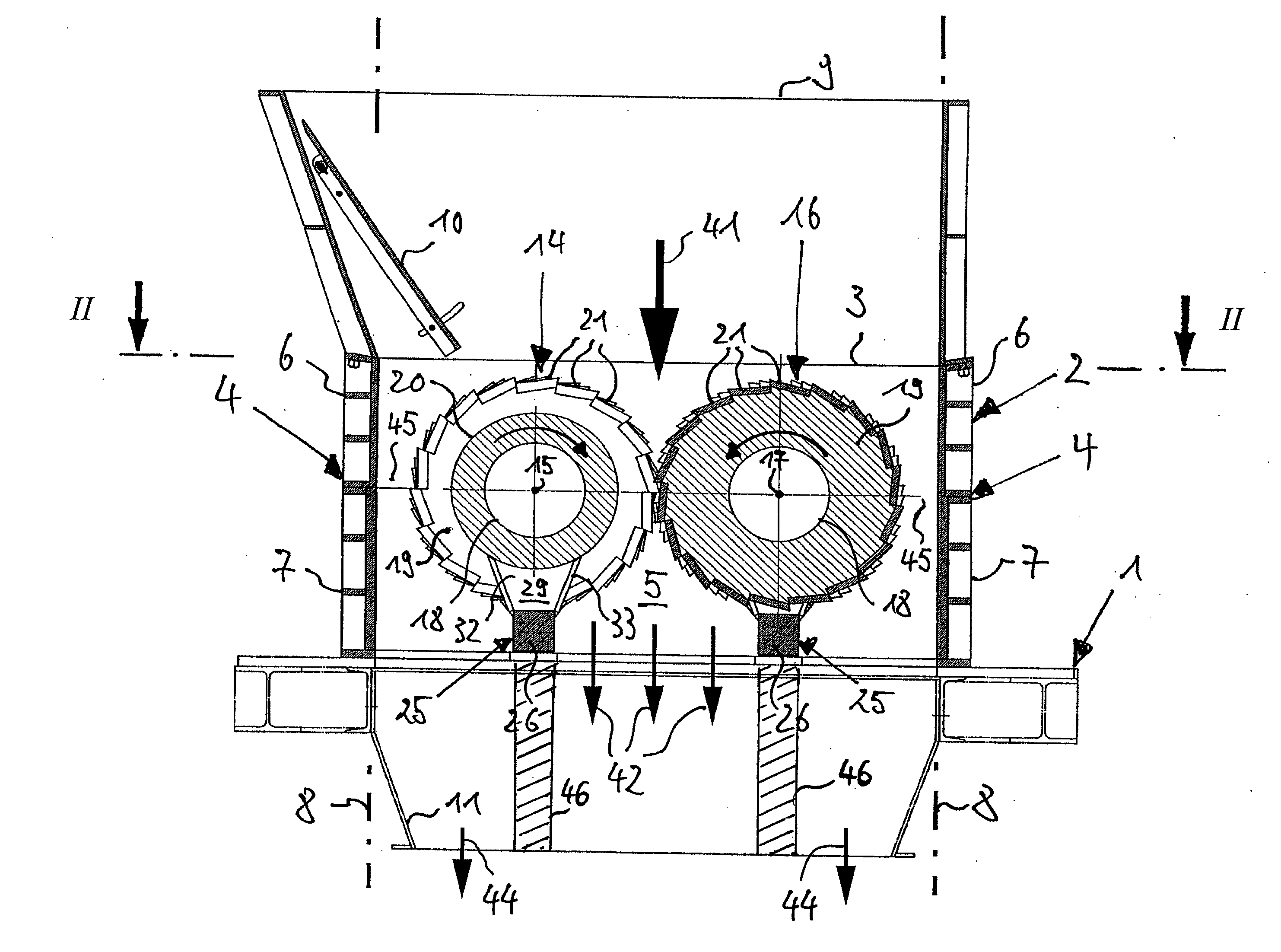
[0015]In an embodiment, the scraping elements are situated immediately downstream from the rotor in the direction of throughflow, i.e. in the dead zone of the rotor. During normal operation of a rotor according to the invention, this prevents the scraping elements from forming flow resistance within the device, and the material therefore flows largely unhindered. In reversing mode, the scraping element arrangement according to the invention enables the feedstock responsible for the disturbance to be automatically removed from the device. This enables the a device according to the invention to be operated with less maintenance work, compared to known devices. Downtimes due to standstill are minimized, which increases the overall economic efficiency of devices according to the invention.
[0016]A further advantage is derived from mounting the scraping elements on a support beam attached to the machine base frame. By directly introducing the forces coming from the scraping elements into the machine base frame, the axially parallel housing walls are easier to construct. In addition to the associated material savings, this makes it possible to design one or both longitudinal walls as swinging doors, which provides fast, easy and excellent accessibility to the cutting tool and also enables maintenance and repair work to be performed quickly and easily. Mounting the scraping elements directly also reduces deformations under load, so that the cutting gap geometry is maintained during comminution.

Problems solved by technology

These portions therefore not only fail to be comminuted, but they also greatly interfere with the smooth comminution of the remaining feedstock.
These portions must therefore be removed from the rotor at regular intervals, which involves painstaking and time-consuming manual labor.
In addition to the labor costs associated therewith, machine down times caused thereby must also be taken into account, which negatively impacts the overall economic feasibility of devices of this type.
The disadvantage of devices of this type is caused by the machine construction.
This is disadvantageous, particularly in reversing mode, since interfering feedstock cannot be automatically removed from the device and therefore causes an operational shutdown.
As in the prior publication cited above, a disadvantage also arises here from the attachment between the counter-knives and the housing walls.
In addition, the counter-knives and cutting tool again form a continuous barrier at the height of the rotors, which makes it impossible in reversing mode to automatically remove interfering feedstock from the device.

Method used


Image

  • Device for comminuting feedstock with scraping elements
  • Device for comminuting feedstock with scraping elements
  • Device for comminuting feedstock with scraping elements

Examples


Embodiment Construction

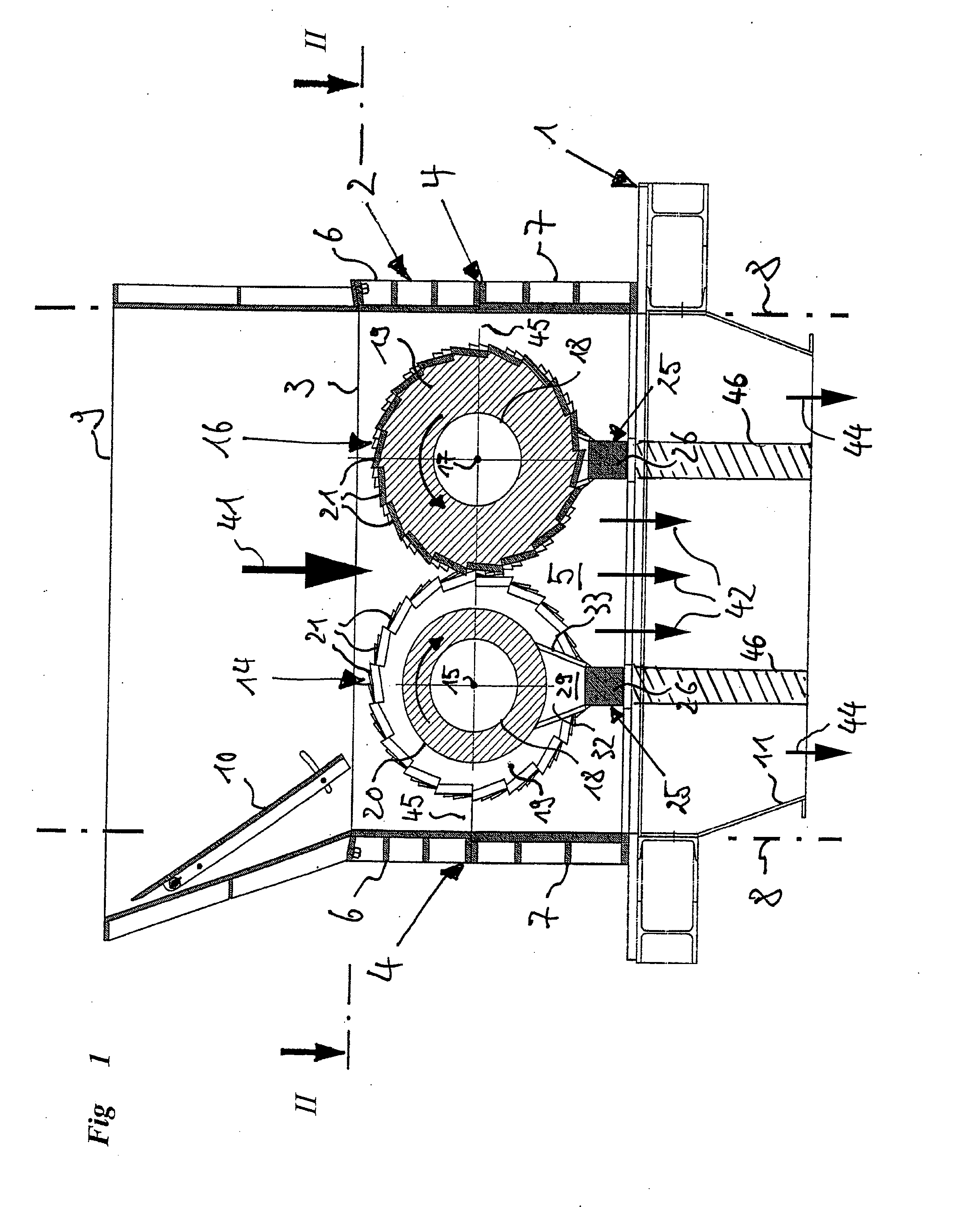
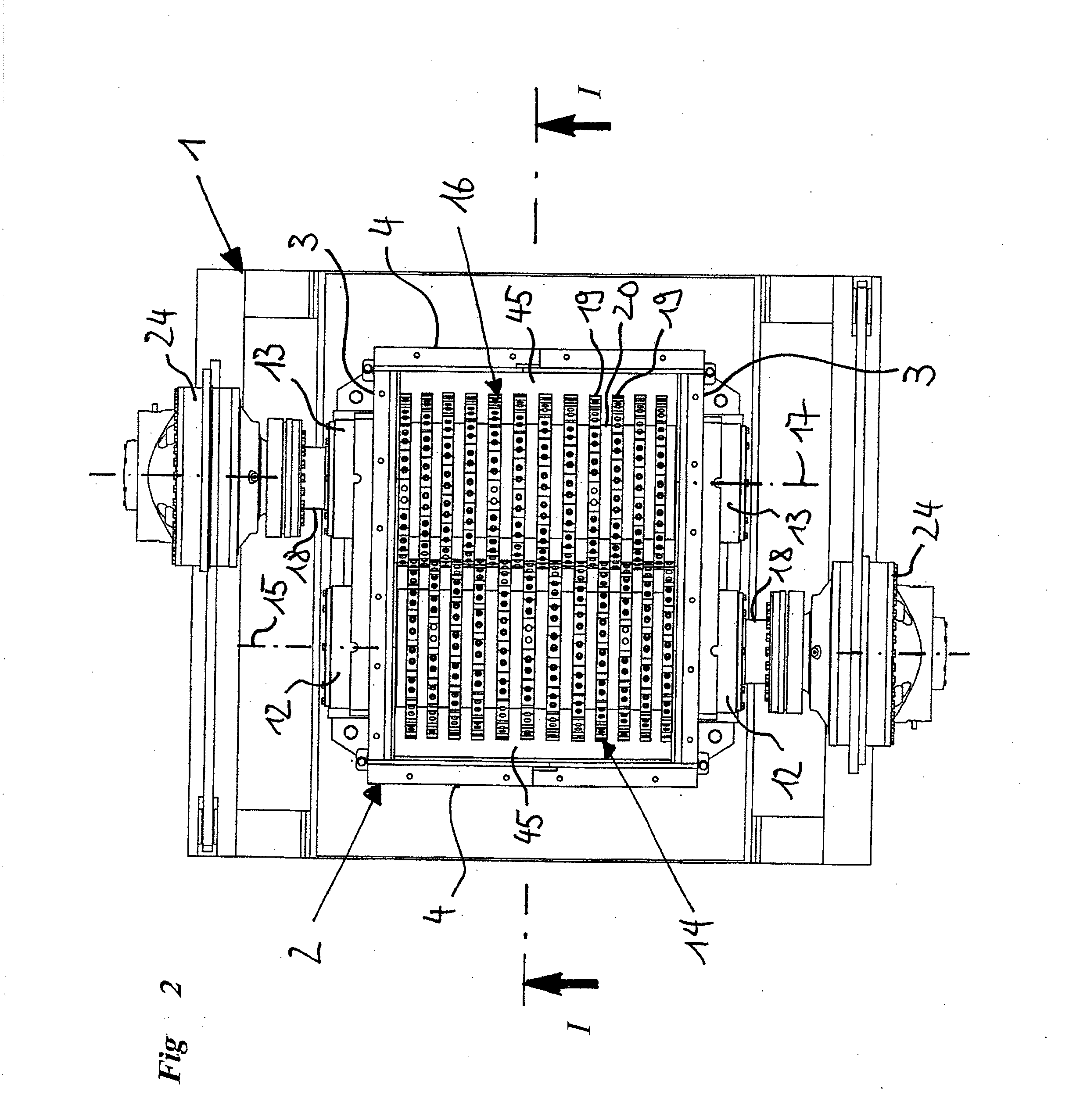
[0031]FIGS. 1 and 2 provide an overview of the device according to the invention. The figures show a frame-like substructure 1, which is composed of steel profiles and on which a rectangular housing 2 rests. Housing 2 is formed by two opposite longitudinal walls 3 and transverse walls 4 connecting longitudinal walls 3 which together surround a comminution chamber 5. Lockable transverse walls 4 are each formed of two parts and have an upper wall part 6 and a lower wall part 7, which may be pivoted individually or together around a vertical pivot axis 8 in order to open housing 2.

[0032]Housing 2, which opens to the top, is adjacent to a material inlet 9, whose left inlet wall in the illustrations is inclined to facilitate loading feedstock into comminution chamber 5 and is equipped with a chute 10, whose angle of inclination is adjustable relative to the vertical. Beneath and adjacent to comminution chamber 5 is slightly hopper-shaped material outlet 11, through which the sufficiently...


PUM


Abstract

A device for comminuting scrappable feedstock by way of cutting or shear-cutting is provided that includes at least one rotor situated within a housing. The rotor has a plurality of rotary disks which are situated at an axial distance from each other, forming spaces, and which are fitted on their circumferences with comminuting tools which interact with additional comminuting tools to perform the comminution work. Stationary scraping elements extend into the spaces in the radial direction. To achieve a largely unhindered flow of stock through the device, it is proposed according to the invention to situate the stationary scraping elements in the dead zone of the at least one rotor with regard to the direction of stock flow.

Description

[0001]This nonprovisional application claims priority under 35 U.S.C. §119(a) to German Patent Application No. DE 10 2009 008 448, which was filed in Germany on Feb. 11, 2009, and which is herein incorporated by reference.BACKGROUND OF THE INVENTION[0002]1. Field of the Invention[0003]The invention relates to a device for comminuting scrappable feedstock by way of cutting or shear-cutting.[0004]2. Description of the Background Art[0005]The comminution of feedstock is a central component of mechanical process engineering, in which a source material is reduced into smaller components by a separation operation. The feedstock is thereby changed in size, shape or composition with regard to its later use. An example of this would be the preparation of waste material, in which the source material must be reduced in size in order to be processed in subsequent processing stations, or in which the feedstock is simultaneously separated into different fractions thereof, following comminution.[0...

Claims


Application Information

Patent Timeline
IPC IPC(8): B02C4/40
CPCB02C18/14B02C18/16B02C18/146
Inventor PALLMANN, HARTMUT
Owner PALLMANN MASCHFAB GMBH & CO KG
Learn More