Multi-layered composite gasket

a composite gasket and multi-layer technology, applied in the direction of machines/engines, other domestic objects, transportation and packaging, etc., can solve the problems of affecting the sealing performance of the gasket, and presenting a possible leakage path for fluids through the gasket body, so as to reduce the buildup of sheer loads, maintain the seal, and relieve the effect of sheer loads

Active Publication Date: 2010-08-19
TENNECO
View PDF9 Cites 34 Cited by
  • Summary
  • Abstract
  • Description
  • Claims
  • Application Information

AI Technical Summary

Benefits of technology

[0012]A gasket assembled according to the techniques of this invention reduces the buildup of sheer loads caused by relative movement between the mating members. The paper layers disposed between the respective perforated cores and the center core can function as slip planes to enable slight lateral shifting of the perforated cores relative to the center core which thereby relieve sheer loads in use without det

Problems solved by technology

However, the head gasket in this application not only seals the combustion chambers, but also various coolant and lubrication flow passages that extend between the cylinder block and head.
Accordingly, designing a gasket to function satisfactorily over an extended duty range can be quite difficult.
Sheer loads are thus created in the body of the gasket, which can weaken and possibly break the rigid glue layers between the perforated metal layers and the central metal core.
It has been observed that sheer loads resisted within the body of the gasket can wea

Method used


Image

  • Multi-layered composite gasket
  • Multi-layered composite gasket
  • Multi-layered composite gasket

Examples


Embodiment Construction

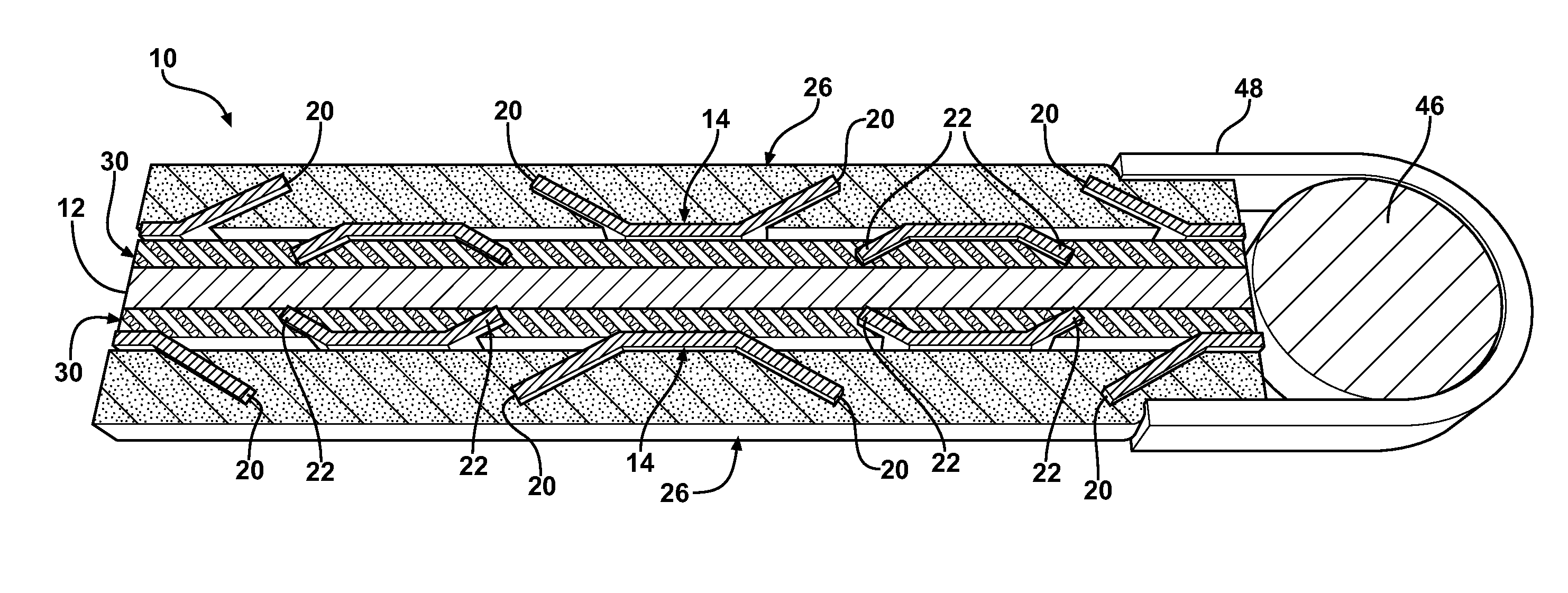
[0025]Referring to the figures, wherein like numerals indicate like or corresponding parts throughout the several views, a gasket according to this invention is generally shown at 10 in FIGS. 4-6. The gasket 10 includes a metallic, preferably steel, center core layer 12 having oppositely facing sides. Preferably, the center core 12 has a generally uniform thickness and is formed without discontinuities or irregularities so as to establish a continuous, uninterrupted barrier throughout the gasket 10. The center core 12 may be supplied in roll form on a coil 36, like that shown in FIG. 9, or in sheet form. The center core 12 may have a thickness ranging between about 0.13 and about 6.35 millimeters. The center core 12 may be provided with a coarse surface finish if the specifications for a particular application so dictate.

[0026]A pair of substantially identical perforated metal core layers, each generally indicated at 14, are arranged on opposite sides of the center core 12. The perf...


PUM

PropertyMeasurementUnit
Thicknessaaaaaaaaaa
Densityaaaaaaaaaa
Metallic bondaaaaaaaaaa

Abstract

A multi-layered composite gasket (10) includes three, preferably metallic cores (12, 14). A solid center core (12) is flanked on both sides by bonded paper layers (30). Perforated cores (14) mechanically interlock with each paper layer (30) through inwardly directed tangs (22). Graphite layers (26) are disposed outside of each perforated core (14) and are mechanically interlocked thereto by outwardly directed tangs (20) extending from the perforated cores (14). When using the gasket (10) material for sealing cylinder heads in internal combustion engines, a fire ring (46) may be affixed with a fire ring holder (48). The gasket (10) can be manufactured by making first and second preform sheets (32) comprised of one perforated core (14) sided with one paper layer (30) and one graphite layer (26). The preform sheets (32) are then bonded to a center core (12) using a heat activated adhesive. Combining rollers (42) compress and densify the layers to form the completed material set which can be stored on a coil (44) or cut into sheets.

Description

CROSS REFERENCE TO RELATED APPLICATIONS[0001]This application claims priority to Provisional Patent Application No. 61 / 152,456 filed Feb. 13, 2009, the entire disclosure of which is hereby incorporated by reference and relied upon.BACKGROUND OF THE INVENTION[0002]1. Field of the Invention[0003]This invention relates to a multi-layered composite gasket and method of making a gasket.[0004]2. Related Art[0005]Gaskets are used in many applications to perfect a fluid-tight seal between two mating members. The gasket is typically clamped between the mating members and held there in compression. In the case of internal combustion engines, many gaskets are used in various capacities. As one example, the head gasket is one which is positioned between the cylinder block and cylinder head of an engine to prevent the leakage of combustion gases from the combustion chambers during use of the engine. However, the head gasket in this application not only seals the combustion chambers, but also var...

Claims


Application Information

Patent Timeline
IPC IPC(8): F16J15/06B32B38/00
CPCB32B3/266B32B9/04B32B15/12B32B37/12F16J15/122B32B2311/00B32B2313/04B32B2317/12B32B2581/00B32B37/20B32B7/12B32B9/007B32B9/041B32B9/06B32B15/18B32B3/08B32B2307/50B32B2605/00F02F11/00F16J15/00F16J15/08
Inventor VIRGIN, WILFORD DEANPONNAVOLU, DEEPAKSHIRILLA, MICHAELSANTIAGO, CARLOSBRANDT, CURTIS ARTHUR
Owner TENNECO
Why Eureka
Try Eureka