
Laminated Electrically Tintable Windows

a technology of electrically tintable windows and laminated windows, applied in the direction of door/window protective devices, instruments, optical elements, etc., can solve the problems of incompatible processing requirements and/or performance compromise, and achieve the effect of enhancing functionality, facilitating installation, and facilitating installation

Inactive Publication Date: 2010-08-19
APPLIED MATERIALS INC
View PDF25 Cites 92 Cited by
  • Summary
  • Abstract
  • Description
  • Claims
  • Application Information

AI Technical Summary

Benefits of technology

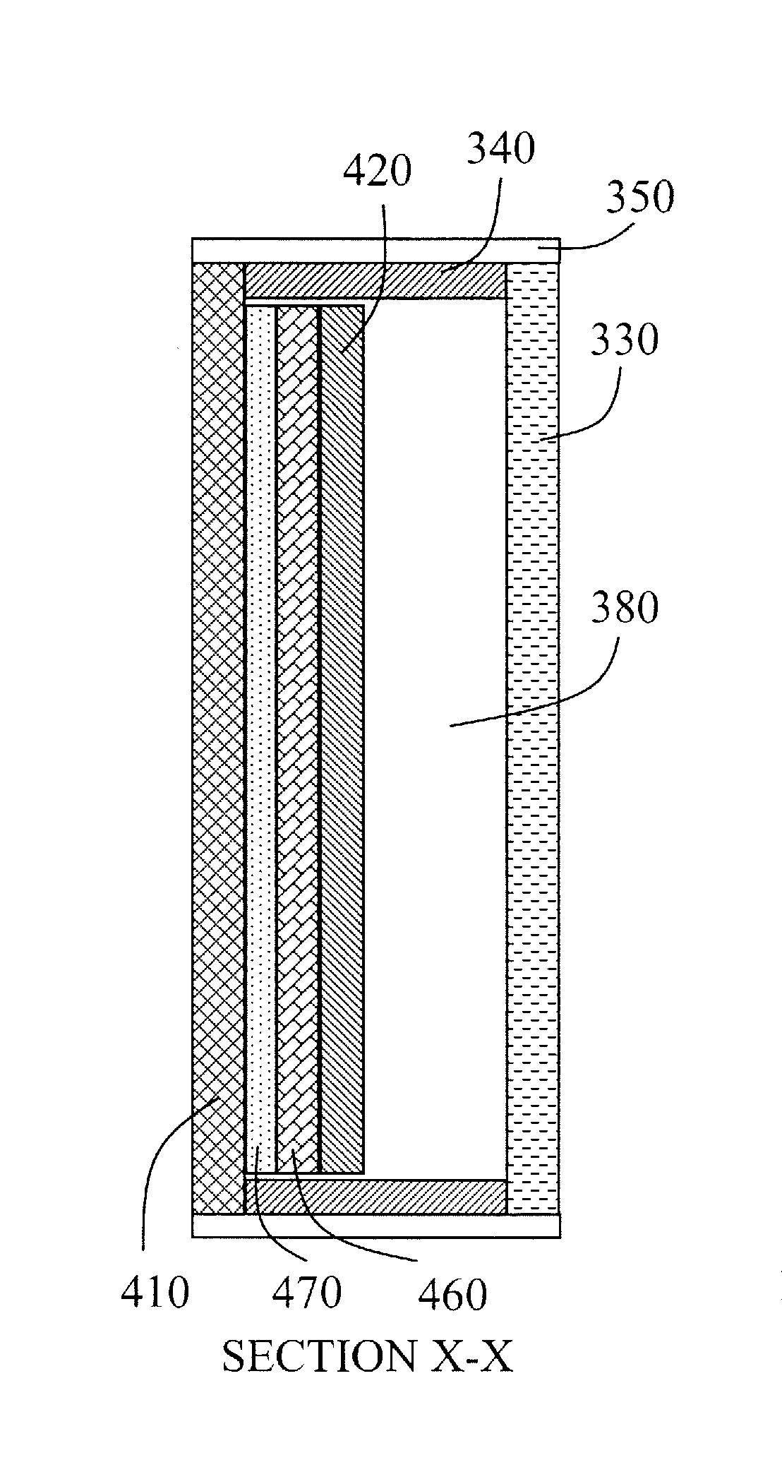
[0010]Embodiments of this invention are based on the concept of (1) separating out various glass functionalities into a number of pieces of glass and (2) exploiting glass lamination technologies to combine the glass pieces to provide an integrated glass product with enhanced functionality. This approach is particularly valuable when the desired different functionalities lead to incompatible processing requirements and / or compromised performance. A method of manufacturing electrically tintable window glass is provided which readily allows for a wide variety of window sizes and functionalities. The method includes fabricating the electrically tintable device independently of the window glass, and lastly laminating the electrically tintable device to the window glass. This approach allows for much greater process flexibility when fabricating the electrically tintable device, as well as providing greater flexibility in the specification of the window glass. These concepts and methods allow for cost effective, high yield and high throughput manufacturing of electrically tintable windows. The electrically tintable window glass fabricated using the methods described herein may be incorporated into IGUs, and other types of architectural glass.
[0011]The approach of embodiments of this invention allows for the electrically tintable devices to be fabricated on a standard size and thickness substrate—all of the thin film processing is done on a single size of glass substrate. This provides a stable production environment suitable for high volume manufacturing with good process control, high throughput and high yield. Only after the individual electrically tintable devices are cut from the substrate is there a need to handle different sized substrates.

Problems solved by technology

This approach is particularly valuable when the desired different functionalities lead to incompatible processing requirements and / or compromised performance.

Method used


Image

  • Laminated Electrically Tintable Windows
  • Laminated Electrically Tintable Windows
  • Laminated Electrically Tintable Windows

Examples


Embodiment Construction

[0022]The present invention will now be described in detail with reference to the drawings, which are provided as illustrative examples of the invention so as to enable those skilled in the art to practice the invention. Notably, the figures and examples below are not meant to limit the scope of the present invention to a single embodiment, but other embodiments are possible by way of interchange of some or all of the described or illustrated elements. Moreover, where certain elements of the present invention can be partially or fully implemented using known components, only those portions of such known components that are necessary for an understanding of the present invention will be described, and detailed descriptions of other portions of such known components will be omitted so as not to obscure the invention. In the present specification, an embodiment showing a singular component should not be considered limiting; rather, the invention is intended to encompass other embodimen...


PUM

PropertyMeasurementUnit
pressureaaaaaaaaaa
pressureaaaaaaaaaa
temperatureaaaaaaaaaa

Abstract

A method of manufacturing electrically tintable window glass with a variety of sizes and functionalities is described. The method comprises: (a) providing a large format glass substrate; (b) fabricating a plurality of electrically tintable thin film devices on the large format glass substrate; (c) cutting the large format glass substrate into a plurality of electrically tintable pieces, each electrically tintable piece including one of the plurality of electrically tintable thin film devices; (d) providing a plurality of window glass pieces; (e) matching each one of the plurality of electrically tintable pieces with a corresponding one of the plurality of window glass pieces; and (f) laminating each of the matched electrically tintable pieces and window glass pieces. The lamination may result in the electrically tintable device either being sandwiched between the glass substrate and the window glass piece or on the surface of the laminated pieces. The electrically tintable device is an electrochromic device.

Description

CROSS-REFERENCE TO RELATED APPLICATIONS[0001]This application is a divisional of, and claims the benefit of, U.S. patent application Ser. No. 12 / 333,676 filed Dec. 12, 2008, which is incorporated by reference herein.FIELD OF THE INVENTION[0002]The present invention relates generally to electrically tintable windows and more specifically to improved manufacturing methods for electrically tintable windows that accommodate a variety of window sizes and functionalities while maintaining high yield, high throughput and low cost.BACKGROUND OF THE INVENTION[0003]Smart windows are glazing units that incorporate devices which have controllable optical and thermal transmission properties. The devices are generally in the form of layers either directly deposited on, or laminated to, the glass surface. Integration of the so-called smart windows into a building provides the opportunity to control internal light levels and temperature by adjusting the optical and thermal properties of the windows...

Claims


Application Information

Patent Timeline
Patent Type & Authority Applications(United States)
IPC IPC(8): G02F1/161G02F1/153G02F1/01G02F1/167G02F1/1333
CPCB32B17/10045B32B17/10055B32B17/10761B32B17/10788B32B17/10981Y10T156/1075E06B9/24E06B2009/2464G02F1/1533Y10S359/90Y10T156/12E06B3/6722B32B17/10513
Inventor KWAK, BYUNG-SUNG LEOHAAS, DIETERBANGERT, STEFANKRISHNA, NETY M.HOFFMANN, WINFRIED
Owner APPLIED MATERIALS INC
Learn More