Hollow type planar illuminatng device

a planar illuminating and light-emitting technology, which is applied in semiconductor devices, lighting and heating apparatus, instruments, etc., can solve the problems of degrading the display quality of liquid crystal illuminated by the backlight unit, unfavorable increased thickness, and uneven brightness or color, so as to reduce the directivity angle, increase diffusion properties, and reduce the effect of directivity angl

Inactive Publication Date: 2010-08-19
HARISON TOSHIBA LIGHTING CORP
View PDF4 Cites 38 Cited by
  • Summary
  • Abstract
  • Description
  • Claims
  • Application Information

AI Technical Summary

Benefits of technology

[0012]According to the present invention, there is provided a hollow type planar illuminating device, including: a reflecting surface member disposed on a bottom surface of a hollow unit case and having a reflecting surface inclined with respect to the bottom surface; a light emitting surface member disposed at a position within the unit case facing the reflecting surface member in parallel to the bottom surface of the unit case; an LED light source unit including a plurality of LEDS arranged to be adjacent to each other on at least either side of a hollow light guide space extending between the light emitting surface member and the reflecting surface member, and emitting light to the hollow light guide space; and alight collecting lens disposed along the LED light source unit to reduce a directivity angle of the light emitted from the LED ...

Problems solved by technology

Therefore, a short distance between a plurality of arranged LEDs and a surface emitting portion causes uneven brightness or color.
If such uneven brightness or color is generated in the LED backlight unit, the display quality of liquid crystal illuminated by the backlight unit is degraded.
However, such an increased thickness is not preferable, which is against a recent tendency of slimness of a liquid crystal display apparatus.
Accordingly, when such white light emitting LEDs are used as a light source, the light emitted from the backlight is perceived as white; however, there is posed a problem of generation of an unmatched color, for example, when ...

Method used


Image

  • Hollow type planar illuminatng device
  • Hollow type planar illuminatng device
  • Hollow type planar illuminatng device

Examples


first embodiment

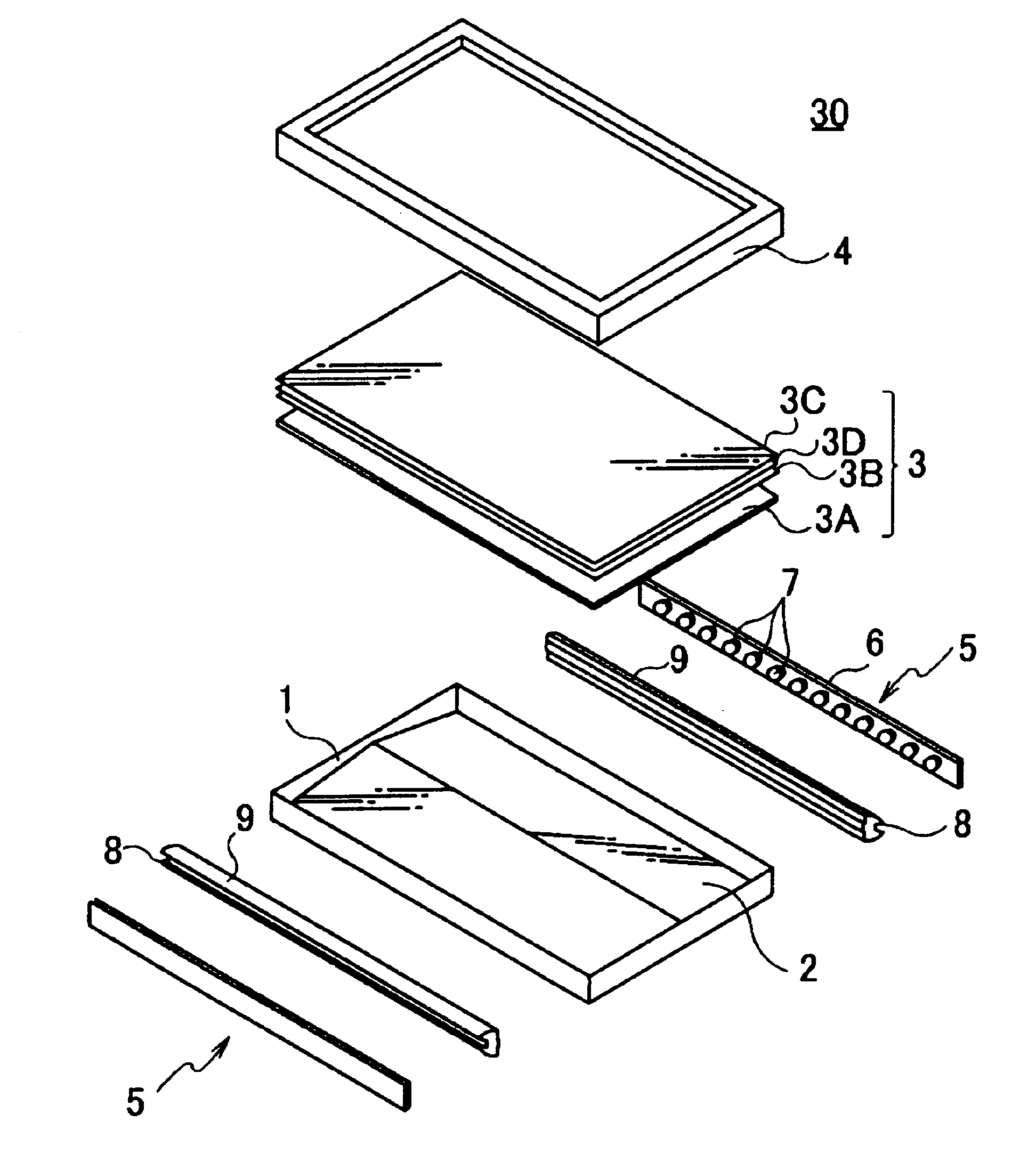
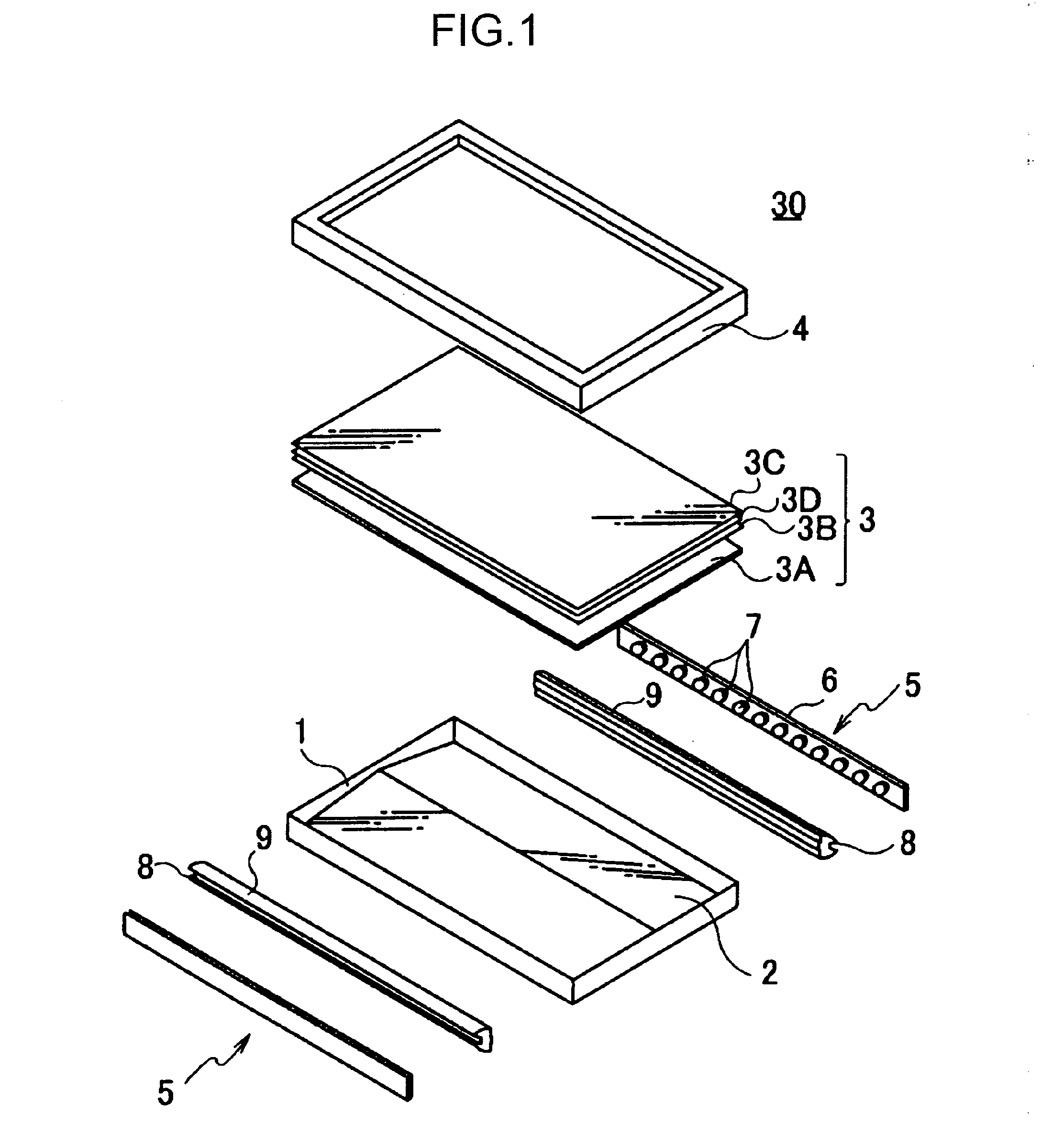
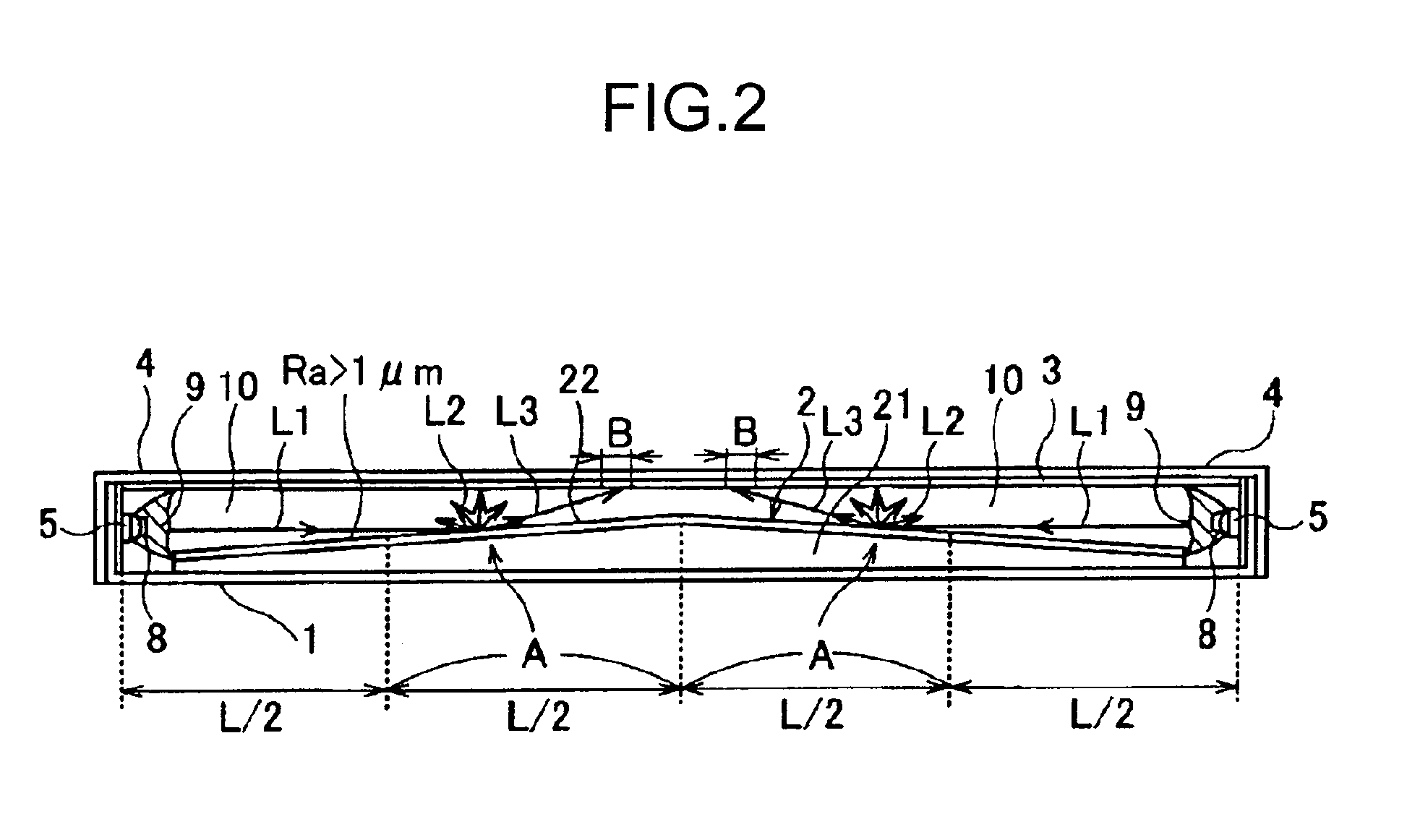
[0025]FIGS. 1 and 2 illustrate a backlight unit 30 for a liquid crystal display apparatus which employs a hollow type planar illuminating apparatus according to a first embodiment of the present invention. In the backlight unit 30, a line in parallel to one side of the unit case 1 in the middle of a bottom surface thereof is defined as a ridge line and a mountain-shaped reflecting surface member 2 having an inclined surface on each of both sides of the ridge line is disposed. On an open surface of the unit case 1, a light emitting surface member 3 is disposed. An open surface of the unit case 1 has a front frame 4 covering a peripheral edge portion of the light emitting surface member 3 and is integrated with the unit case 1. The unit case 1 is formed from metal having high thermal conductivity, such as aluminum alloy.

[0026]A space extending between the reflecting surface member 2 and the light emitting surface member 3 in the unit case 1 is a hollow light guide space 10 rectangular...

second embodiment

[0039]Referring now to FIGS. 6A and 6B, a backlight unit 30A according to a second embodiment of the present invention will be described below. The structure of the backlight unit 30 according to the present embodiment is substantially the same as that of the first embodiment illustrated in FIGS. 1 and 2. Accordingly, commonly employed elements are assigned with the same reference symbols.

[0040]A reflecting surface member 2C in the backlight unit 30A according to the present embodiment is formed so that surface roughness Ra thereof gradually increases as the reflecting surface member goes farther toward the ridge line from an edge end adjacent to the LED light source unit 5 as shown in a graph of FIG. 6B. That is to say, the surface roughness Ra of the reflecting surface member 2C is defined to be Ra>1 μm and a value nearest to 1 μm at the edge end x=0, to be maximum at a central ridge position x=xmax of the reflecting surface member 2C and to gradually increase as a function define...

third embodiment

[0045]Referring to FIG. 8, a backlight unit 30B according to a third embodiment of the present invention will be described below. The backlight unit 30B in the present embodiment has a single incidence type structure in which a reflecting surface member 2D of a single slope structure is attached onto the bottom portion of the unit case 1A and the LED light source unit 5 is installed on a single side of the unit case 1A. That is to say, the backlight unit 30B is a single incidence type backlight unit that allows light to be incident into the hollow light guide space 10 from the LEDs of the LED light source unit 5 and reflects the light on the light emitting surface member 3 side with the reflecting surface member 2D.

[0046]The present embodiment as well uses a member having a surface state used in the first embodiment, that is, a reflecting surface member 2D set so that the surface roughness Ra satisfies Ra>1 μm. In the present embodiment, other configurations are common to the first ...


PUM


Abstract

Provided is a hollow type planar illuminating device having uniform luminance distribution over the entire light emitting surface. A reflecting surface member (2) is arranged on the bottom side of a hollow unit case (1), a light emitting surface member (3) is arranged on the side facing the reflecting surface member of the unit case, and a space sandwiched between the reflecting surface member and the light emitting surface member of the unit case is permitted to be a hollow light guide space (10). An LED light source unit (5) wherein many LEDs are mounted in a row on a wiring board is arranged adjacent to the both sides or one side of the hollow light guide space so that light is emitted to the hollow light guide space. Between the LED light source unit and an end surface of the hollow light guide space, a light collecting lens (9) is arranged. The light collecting lens reduces the directivity angle of light emitted from the LED light source unit in the device thickness direction. Thus, a hollow type planar illuminating device (30) is formed. The surface roughness (Ra) of the surface of the reflecting surface member (2) facing the hollow light guide space (10) is set to satisfy the inequalities of 1 μm<RA<10 μm.

Description

BACKGROUND OF THE INVENTION[0001]1. Field of the Invention[0002]The present invention relates to a hollow type planar illuminating device configured to emit illuminating light of uniform luminance distribution from a light emitting surface thereof such as a backlight unit fora liquid crystal display apparatus, for example.[0003]2. Description of the Related Art[0004]In recent years, a light source of a backlight unit for a liquid crystal display apparatus has accelerated a move toward replacement of a cold cathode discharge lamp with an LED. This is because the LED is suitable as an environment-conscious light source without use of mercury that is harmful material or because power consumption of the LED can be significantly small due to recent drastic enhancement of LED light emitting efficiency. A backlight unit having an LED as a light source has been used mostly for a small-sized apparatus such as a cellular phone or mobile terminal until now. However, the backlight unit having t...

Claims


Application Information

Patent Timeline
IPC IPC(8): F21V7/00
CPCF21V7/0091F21V7/22F21V13/04F21Y2101/02G02B6/0096G02B6/0046G02B6/0051G02B6/0055G02B6/003F21Y2115/10
Inventor TSUCHIYA, RYUJIKAWASAKI, YOJI
Owner HARISON TOSHIBA LIGHTING CORP
Why Eureka
Try Eureka