Heated fluid conduits, systems and methods

a fluid conduit and conduit technology, applied in the field of fluid conduits, can solve the problems of affecting the operation affecting the operation efficiency of the drill rig, and the difficulty of fluid passing through the coupling, so as to facilitate the operation of a semi-conductive heating sleeve, the fluid viscosity of the fluid is reduced

Active Publication Date: 2010-08-19
THE GATES CORP
View PDF16 Cites 22 Cited by
  • Summary
  • Abstract
  • Description
  • Claims
  • Application Information

AI Technical Summary

Benefits of technology

[0009]The semiconductive resistive heated hose is composed of an electrically conductive rubber tube on the inside of the hose with a resistance of 2 to 15 ohms per foot. It can also be composed of a composite, braided, carbon fiber tensile member or a carbon fiber sleeve that is pushed over the hose assembly after the hose is constructed. This tube or sleeve, because of the electrical resistance, will heat up when a voltage is applied to it in such a manner as to provide an electrical path. The heat that is produced in the tube or sleeve will warm the internal fluid lowering the viscosity of the fluid and allowing it to flow without damaging components. This tube or sleeve can be constructed into or on a conventional high pressure, wire reinforced, hydraulic hose, or the carbon fiber can also be the tensile member of the hose. When electricity is connected to the tube or sleeve electricity will flow through the tube of sleeve to ground and the result will be a heated hose that is in contact with the fluid.
[0010]To facilitate operation of a semi-conductive heating sleeve it may be advantageous to warm the couplings associated with the hose or tube. If the couplings are not warmed with the hose, it may be difficult for fluid may to pass through the couplings. Therefore, it may be advantageous to heat the couplings along with the hose, such as by extending the heating sleeve over the hose couplings. Also, preferably, the hose couplings are insulated and protected along with the wiring providing power to the heating sleeve.
[0018]Advantageously, the present sleeve heating system affords an ability to tailor the resistance per foot at assembly to meet heating requirements needed for individual conduit lengths. By using a sleeve with different resistance levels, such as may be expressed in ohms per foot one may lower the resistance per foot for a longer length assembly.

Problems solved by technology

This is a rather inefficient and inflexible solution that requires a complete redesign of the fluid line to change its heating properties.
This cold weather has an adverse effect on equipment and hydraulic components on a drill rig.
If the couplings are not warmed with the hose, it may be difficult for fluid may to pass through the couplings.

Method used


Image

  • Heated fluid conduits, systems and methods
  • Heated fluid conduits, systems and methods
  • Heated fluid conduits, systems and methods

Examples


Embodiment Construction

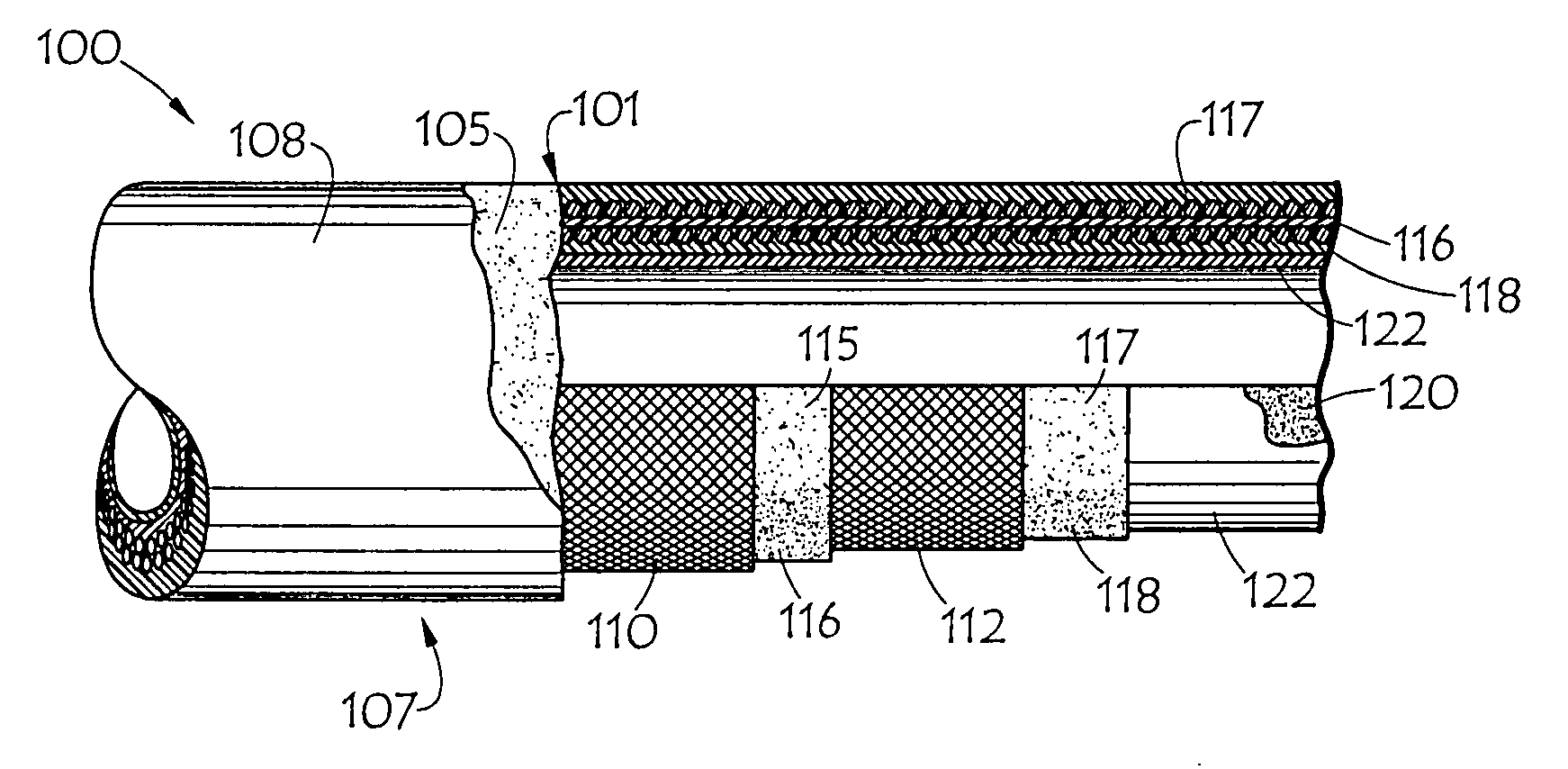
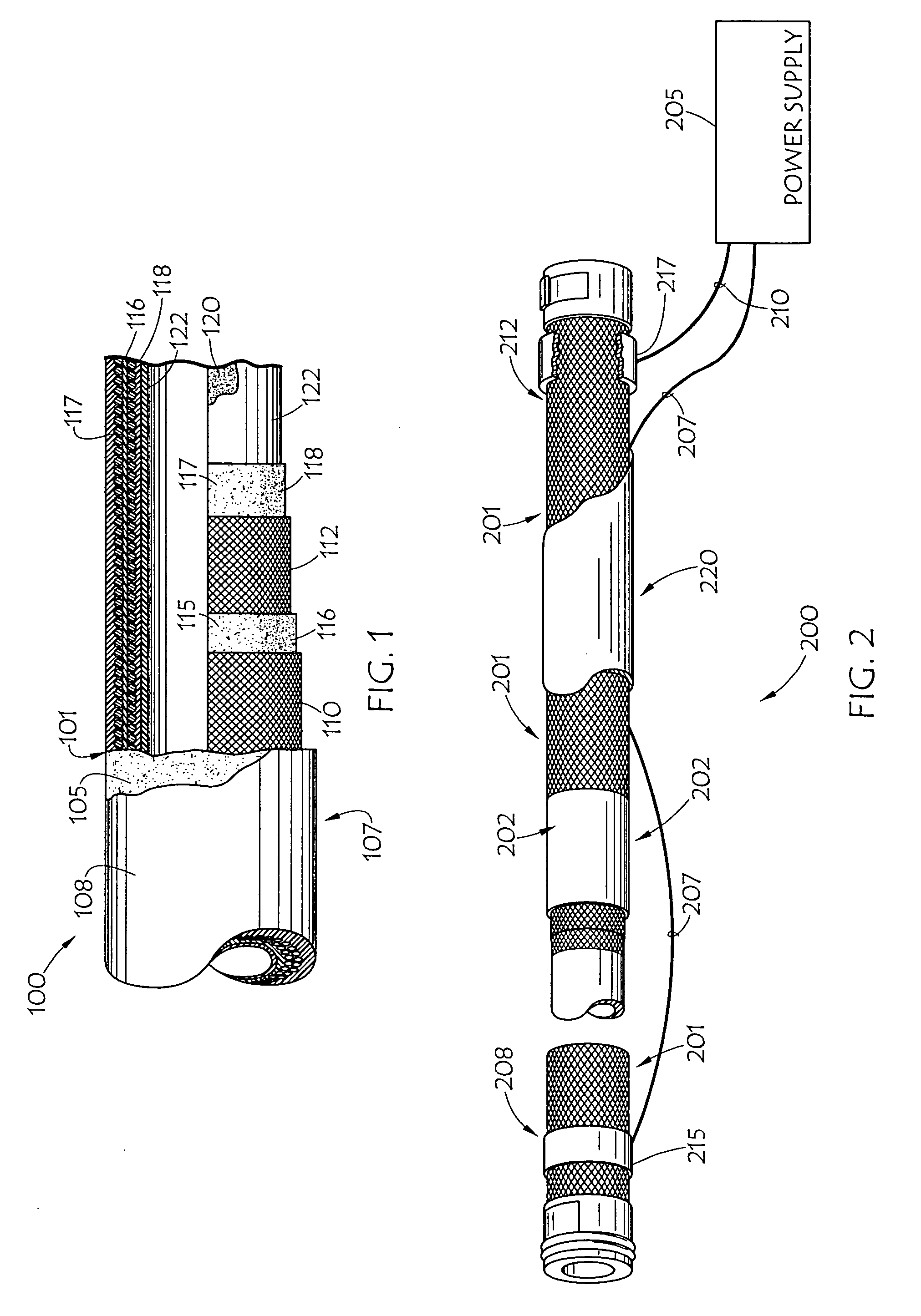
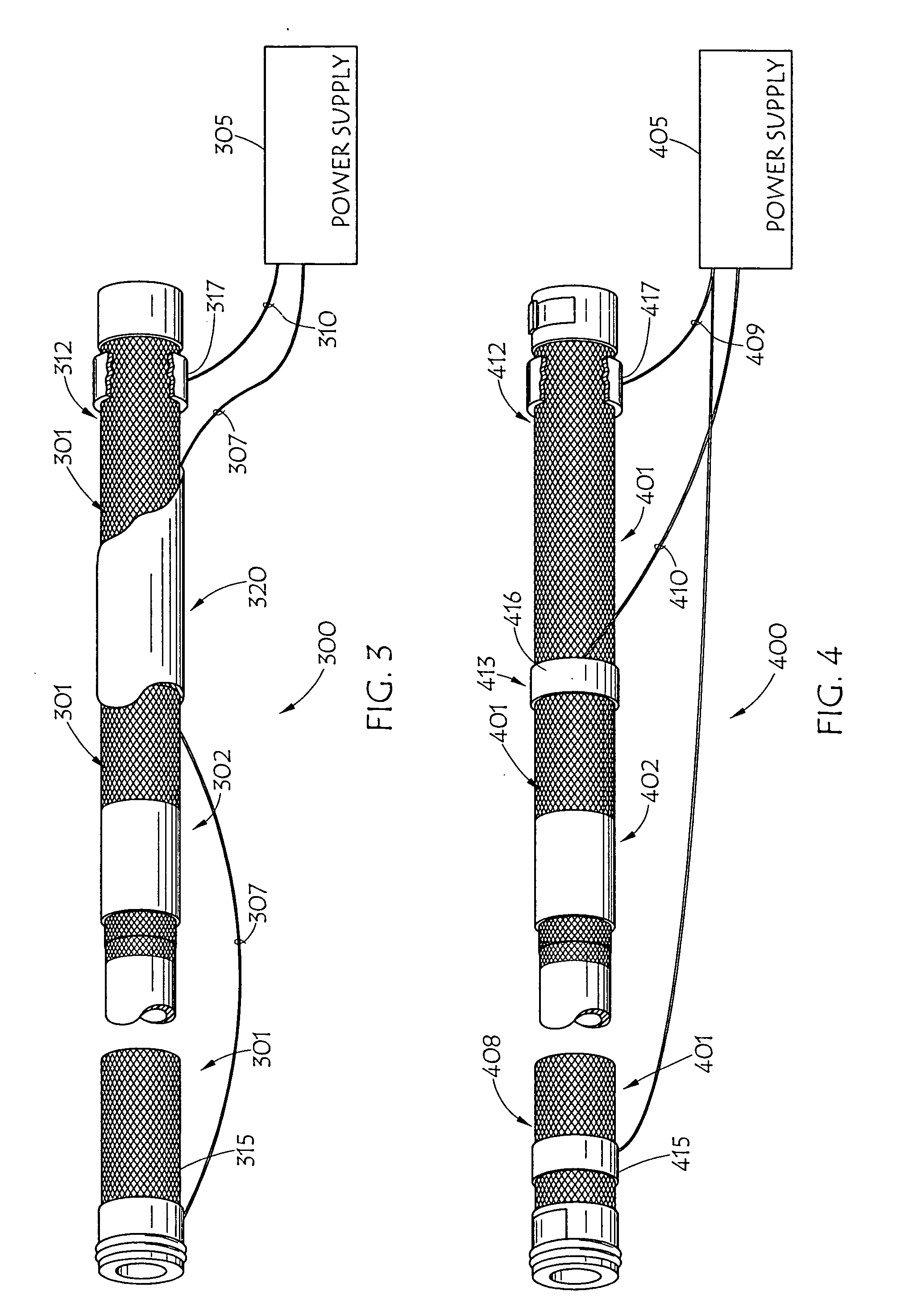
[0029]InFIG. 1 a fragment view of an embodiment of heated fluid conduit 100 is shown. Illustrated fluid conduit 100, a hose, is shown having body 101 with semi-conductive material disposed therein. The semi-conductive may take the form of “chopped” material 105, disposed in cover 108; woven or braided semi-conductive textile material 110 and / or 112; “chopped” material 115 and / or 117, disposed in intermediate hose layers 116 and 118; and / or “chopped” material 120, disposed in tube 122. In the illustrated example of FIG. 1 this conductive material is intended to be illustrated as carbon fiber reinforcement material. Preferably, these carbon fiber threads act as tensile reinforcement material in illustrated hose 100. Electrical power, such as may be provided through the electrical system of a vehicle or piece of equipment may be supplied to each end of conduit 100 such as through conductive wires, or the like, electrically coupled to the hose to provide a voltage across conduit 100 and...


PUM


Abstract

A heated fluid conduit has a body with a semi-conductive material disposed therein with an electrical power supply coupled to the conduit to provide a voltage across the conduit and a current therethrough, heating the fluid conduit. A fluid conduit heating system comprises a semiconductive sleeve disposed over a fluid conduit and an electrical power supply coupled to the ends of the sleeve to provide a voltage across the sleeve and a resulting current through the semiconductive sleeve, heating the sleeve and conduit Alternatively, one terminal of the electrical power supply is coupled to each end of the sleeve or conduit, and another terminal of the electrical power supply is coupled to the sleeve or conduit therebetween, to provide parallel heating circuits.

Description

BACKGROUND OF THE INVENTION[0001]1. Field of the Invention[0002]This invention relates generally to fluid conduits such as hoses and tubes, more particularly to heated fluid conduits, and specifically to fluid conduits heated using semiconductive resistance heating.[0003]2. Description of the Prior Art[0004]Selective Catalytic Reduction (SCR) vehicles, referred to in Europe as Euro V vehicles, are diesel powered motor vehicles which are compatible with the use of an operating fluid to reduce emissions. Typically, the SCR vehicle has a urea tank, separate from the fuel tank, which is used to carry an operating fluid such as an automotive urea solution, or the like. Automotive Urea Solution (AUS) is a solution of high purity urea in de-mineralized water. AUS is stored in a urea tank of an SCR vehicle and is sprayed into the exhaust gases of the vehicle in order to convert oxides of nitrogen into elementary nitrogen and water. An SCR vehicle may then advantageously satisfy various emis...

Claims


Application Information

Patent Timeline
Patent Type & Authority Applications(United States)
IPC IPC(8): F16L53/00F16L53/37
CPCF16L53/007F16L53/37H05B3/145H05B2203/021
Inventor ELLIS, MICHAEL H.DEANS, TIMOTHYTWAROG, EVANGILBREATH, DONALD R.BOLGER, WALKERSAUPE, TIM
Owner THE GATES CORP
Why Eureka
Try Eureka