

Liquid Sealed Mount
a technology of liquid sealing and mounts, applied in the direction of shock absorbers, machine supports, mechanical apparatus, etc., can solve the problems of poor ride quality, increased vertical rigidity, impaired anti-vibration effect, etc., and achieve the effect of superior anti-vibration characteristics
- Summary
- Abstract
- Description
- Claims
- Application Information
AI Technical Summary
Benefits of technology
Problems solved by technology
Method used
Image

Examples
first exemplary embodiment
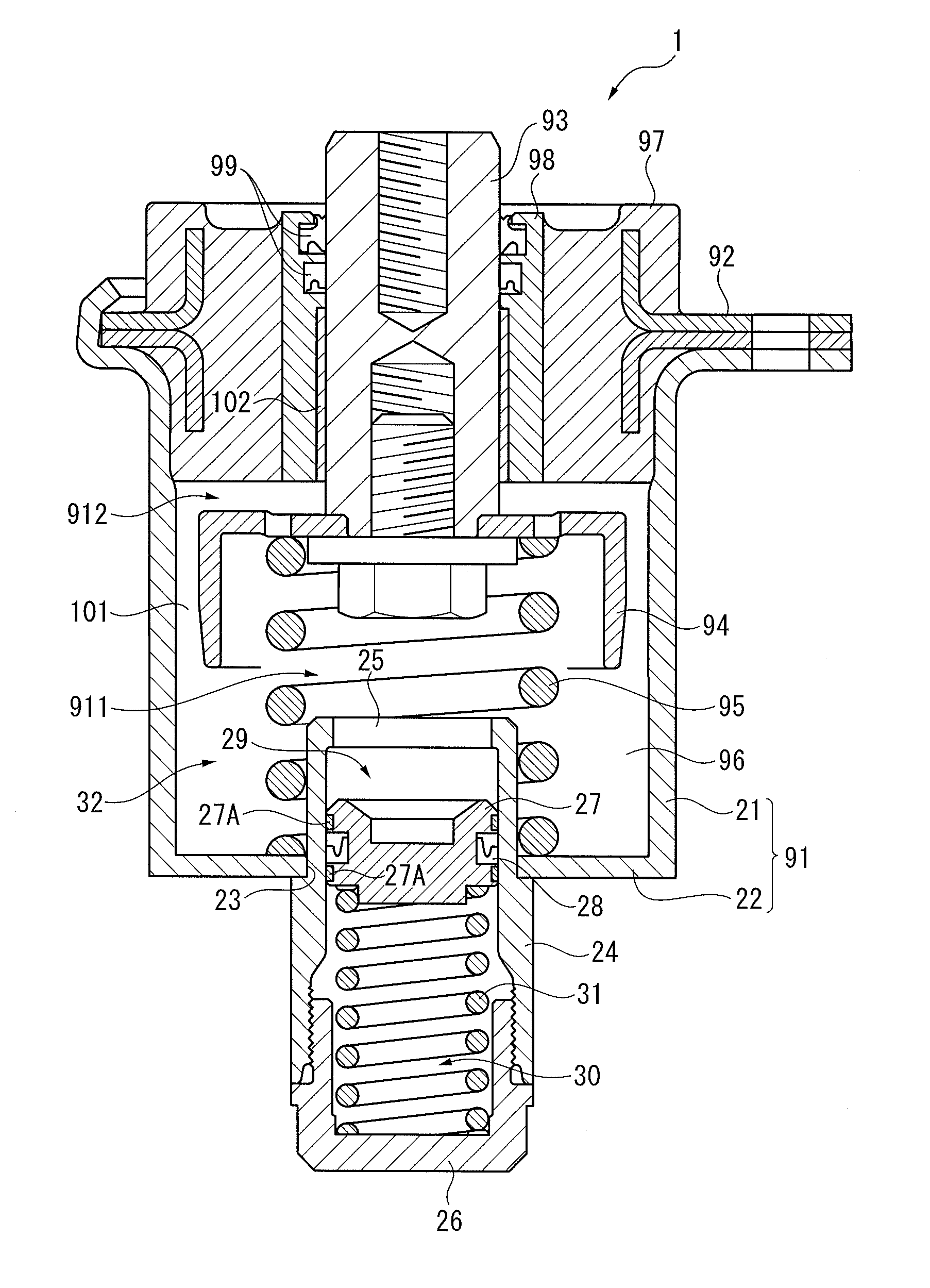
[0075]FIG. 1 shows a hydraulic mount 1 according to a first exemplary embodiment of the invention. In the hydraulic mount 1, a container 91 includes a cylindrical container body 21 and a disk-shaped bottom 22. The container body 21 and the bottom 22 are joined to each other.
[0076]A through hole 23 vertically penetrates the center of the bottom 22. A cylindrical cylinder 24 is coupled to the through hole 23. The upper side of the cylinder 24 is inserted in the container 91 and an opening 25 formed in the upper end of the cylinder 24 opens in a lower fluid chamber 911 defined in the container 91. The inserted portion of the cylinder 24 in the container 91 also functions as a part of a receiving potion for a spring 95.
[0077]The lower side of the cylinder 24 is closed by a cap 26 that is threadedly connected via a seal ring (not shown). A vertically slidable free piston 27 is located in the cylinder 24. A pair of bearings 27A and a seal ring 28 are attached to the free piston 27 to seal...
second exemplary embodiment
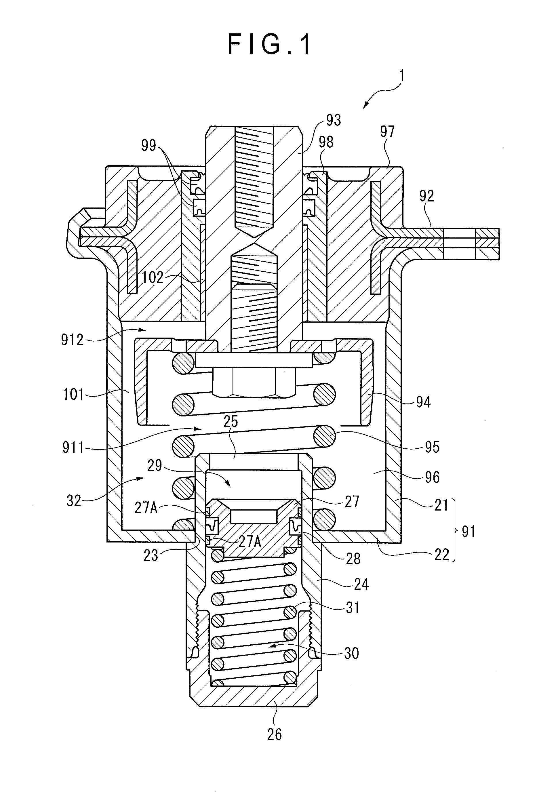
[0084]FIG. 2 shows a hydraulic mount 2 according to a second exemplary embodiment of the invention. The hydraulic mount 2 is provided with a compressed air 33 that is sealed in the air chamber 30 in place of the coil spring 31, and an air valve 34 (English valve type or the like) for injecting the compressed air 33 into the air chamber 30. The free piston 27 and the compressed air 33 form the pressurizer according to the invention. In light of the above arrangement, the second exemplary embodiment is structurally different from the first exemplary embodiment. However, the other arrangements, such as the high-viscosity fluid 96 that is liquid-tightly sealed, are the same as those of the first exemplary embodiment.
[0085]The first exemplary embodiment uses the coil spring 31, so that the spring length may be increased so as to increase the biasing force. Such an increase in the spring length may increase the length of the cylinder 24. In contrast, this exemplary embodiment uses the com...
third exemplary embodiment
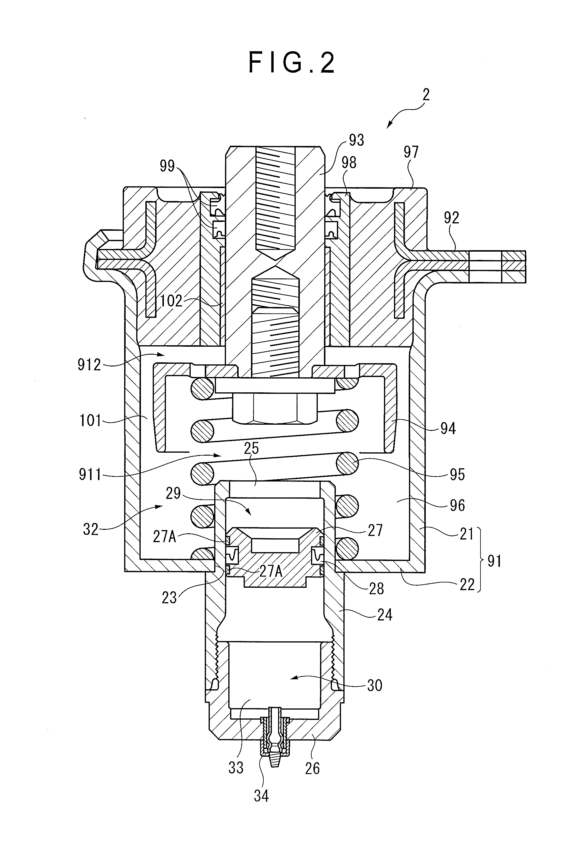
[0087]FIG. 3 shows a hydraulic mount 3 according to a third exemplary embodiment of the invention. In the hydraulic mount 3, a large-diameter through hole 23 formed through the bottom 22 is used as a flow hole for the high-viscosity fluid 96. The secondary fluid chamber 29 below the bottom 22 is formed by a elastically-deformable thin rubber film 35 that closes the through hole 23.
[0088]A cap 26 is attached to the lower surface of the bottom 22 using a bolt to cover the rubber film 35 from below. The circumference of the rubber film 35 is inserted in a groove 22A formed in the bottom 22 to be held between the bottom 22 and the cap 26. The circumference of the rubber film 35 is an oil seal, so that the high-viscosity fluid 96 in the secondary fluid chamber 29 is kept from leaking. The upper side of the inner space of the cap 26 is covered by the rubber film 35 to function as the air chamber 30 into which the compressed air 33 is injected from the air valve 34.
[0089]In this exemplary ...
PUM
 Abstract
Description
Claims
Application Information