Method of fracturing subterranean formations with crosslinked fluid

a technology of fluid and subterranean formation, which is applied in the direction of fluid removal, chemistry apparatus and processes, and wellbore/well accessories, etc., can solve the problem of rapid reduction of the viscosity of the fluid, and achieve the effect of increasing the viscosity

Active Publication Date: 2015-11-24
BAKER HUGHES HLDG LLC
View PDF95 Cites 12 Cited by
  • Summary
  • Abstract
  • Description
  • Claims
  • Application Information

AI Technical Summary

Benefits of technology

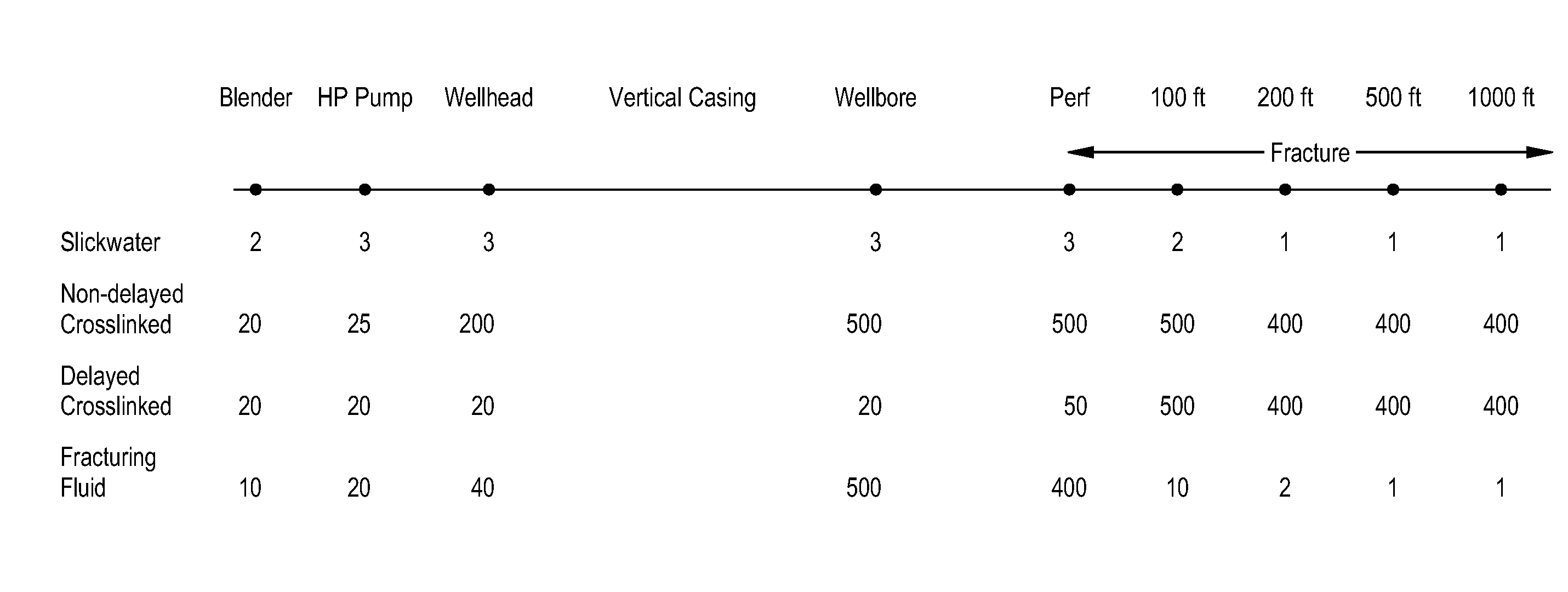
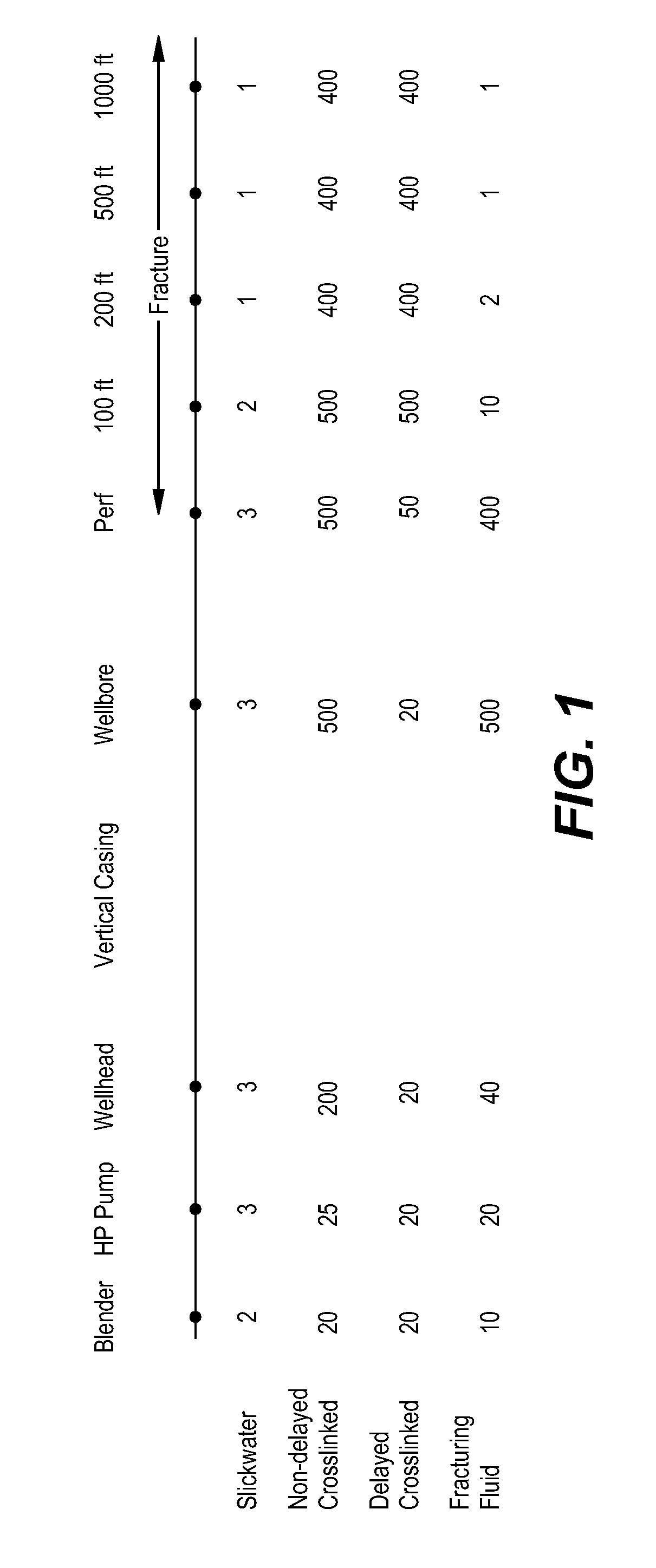
[0012]A method of fracturing having particular applicability in tight gas reservoirs consists of mixing water and a viscosifying polymer, crosslinking agent and proppant and introducing the viscous fluid into the wellhead. The viscosity of the fracturing fluid when pumped into the wellhead may be between from about 10 to about 120 cP at a temperature range between from about 80° F. to about 125° F. Increased viscosity at the surface protects the surface equipment when pumping the suspended proppant into the wellhead. In addition, the viscous nature of the fracturing fluid enables the fluid to transport the proppant to the perforating sites in the wellbore while minimizing settling.
[0013]The loading of the hydratable polymer in the fracturing fluid is from about 6 to about 18 pptg, preferably from about 6 to about 12 pptg. The low loading of the viscosifying polymer in the fracturing fluid causes the viscosity of the fluid to rapidly decrease upon entering the entrance site of perforation.

Problems solved by technology

The low loading of the viscosifying polymer in the fracturing fluid causes the viscosity of the fluid to rapidly decrease upon entering the entrance site of perforation.

Method used


Image

  • Method of fracturing subterranean formations with crosslinked fluid
  • Method of fracturing subterranean formations with crosslinked fluid
  • Method of fracturing subterranean formations with crosslinked fluid

Examples


example 1

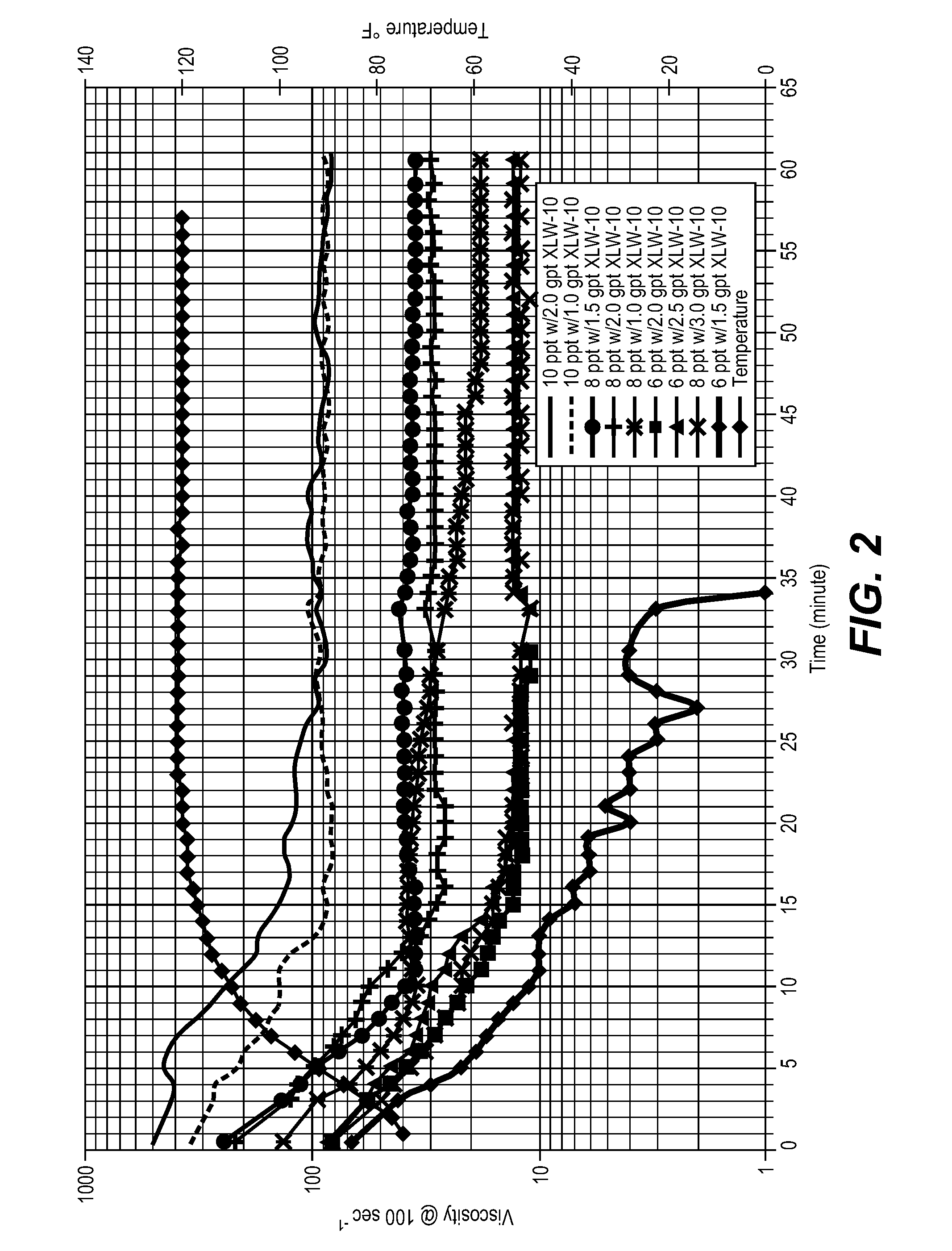
[0045]A fluid was formulated by mixing at room temperature in a blender underivatized guar having an intrinsic viscosity greater than 16 dL / g, commercially available from Baker Hughes Incorporated as GW-2, a borate crosslinker, commercially available from Baker Hughes Incorporated as XLW-10. The loading of the polymer in the fluid varied to be between 6 and 10 pptg (pounds per thousand gallons). The amount of crosslinker in the fluid was varied to be between 1.0 and 3.0 gptg (gallons per thousand gallons). The fluid was buffered to a pH of 9.0. About 30 ml of the fluid was then placed into a Fann 50 viscometer cup having a bob (BX5) and rotor (R1) cup assembly. The cup was then placed on a Fann 50 viscometer. The sample was sheared by a rate sweep of 100 sec−1 for about 1 minute. FIG. 2 shows the results wherein 10 pptg of the fluid with 1 and 2 gptg XLW-10 had initial viscosities of 500 cP and 350 cP, respectively, declining after 5 minutes to about 400 cP and 200 cP, respectively,...

example 2

[0046]A fluid was formulated by adding GW-2 to water in a blender at room temperature and then adding to the fluid a borate crosslinker, commercially available from Baker Hughes Incorporated as XLW-32. A 10% caustic solution (sodium hydroxide) was then added until pH of the fluid was about 9 and the crosslinked fluid formed in approximately 5 seconds. The loading of the polymer in the fluid was between from 0.5 gptg to 2.0 gptg. The amount of crosslinker in the fluid was varied to be between 1.25 gptg and 1.75 gptg. About 30 ml of a 10 pptg fluid was then placed into a Fann 50 viscometer cup having a bob (BX5) and rotor (R1) cup assembly. The cup was then placed on a Fann 50 viscometer. The sample was sheared by a rate sweep of 100 sec−1 for about 1 minute. The stresses associated to each rate were used to calculate the power law indices n and K; n refers to flow behavior index and K refers to consistency index set forth in the American Petroleum Institute's Bulletin RP-39. The flui...

example 3

[0047]A fluid was formulated by mixing at a temperature range of from 75° F. to 150° F. in a blender water, from 2.0 to 3.0 underivatized guar having an intrinsic viscosity greater than 16 dL / g, commercially available from Baker Hughes Incorporated as GW-2LDF and 3 gpt of a self-buffering borate crosslinker, commercially available from TBC-Brinadd as PfP BXL 0.2. The pH of the fluid was buffered to 9.0. About 30 ml of the fluid was then placed into a Fann 50 viscometer cup having a bob (BX5) and rotor (R1) cup assembly. The cup was then placed on a Fann 50 viscometer. The sample was subjected to a shear rate of 511 sec−1. FIG. 4 shows the viscosity profiles of fluids having 8, 10 and 12 pptg. As illustrated, the crosslinked fluid viscosities of each of the example formulations were reduced by 40% to 60% due to increasing the fluid temperature from 75° F. to 150° F.


PUM

PropertyMeasurementUnit
apparent viscosityaaaaaaaaaa

Abstract

Subterranean formations, such as tight gas formations, may be subjected to hydraulic fracturing by introducing into the formation a fracturing fluid of an aqueous fluid, a hydratable polymer, a crosslinking agent and proppant. The fluid enters the reservoir through an entrance site. The apparent viscosity of the fluid decreases distally from the entrance site such that at in situ conditions:(a) the apparent viscosity of the fracturing fluid 100 feet from the entrance site is less than 10 percent of the apparent viscosity of the fracturing fluid at the entrance site;(b) the apparent viscosity of the fracturing fluid 15 minutes after introduction into the entrance site is less than 15% of the apparent viscosity of the fracturing fluid at the entrance site; and / or(c) the apparent viscosity of the fracturing fluid is less than 10 cP within 15 minutes after being introduced through the entrance site.

Description

[0001]This application is a continuation-in-part application of U.S. patent application Ser. No. 12 / 642,662, filed on Dec. 18, 2009.FIELD OF THE INVENTION[0002]The invention relates to a method of fracturing a subterranean formation with an aqueous fluid which contains a hydratable polymer and a crosslinking agent wherein the apparent viscosity of the fluid decreases distally from the entrance site of the reservoir.BACKGROUND OF THE INVENTION[0003]Hydraulic fracturing often requires the use of well treating materials capable of enhancing the production of fluids and natural gas from low permeability formations. In a typical hydraulic fracturing treatment, a fracturing treatment fluid containing a solid proppant is injected into the formation at a pressure sufficiently high enough to cause the formation or enlargement of fractures in the reservoir. The fractures radiate outwardly from the wellbore, typically from a few meters to hundreds of meters, and extend the surface area from wh...

Claims


Application Information

Patent Timeline
Patent Type & Authority Patents(United States)
IPC IPC(8): E21B43/267C09K8/80C09K8/90C09K8/68
CPCE21B43/267C09K8/685C09K8/80C09K8/805C09K8/90
Inventor BELL, CHARLES ELMERBRANNON, HAROLD DEAN
Owner BAKER HUGHES HLDG LLC
Why Eureka
Try Eureka