
Intraocular lens configured to offset optical effects caused by optic deformation

a technology of optical effects and lenses, applied in intraocular lenses, instruments, medical science, etc., can solve the problems of reducing the optical performance of lenses, traditional iol designs have not considered the optical effect of deformation, etc., to reduce the effect of compression, thinner lenses, and reduced stiffness of haptics

Inactive Publication Date: 2010-08-19
ALCON RES LTD
View PDF3 Cites 37 Cited by
  • Summary
  • Abstract
  • Description
  • Claims
  • Application Information

AI Technical Summary

Benefits of technology

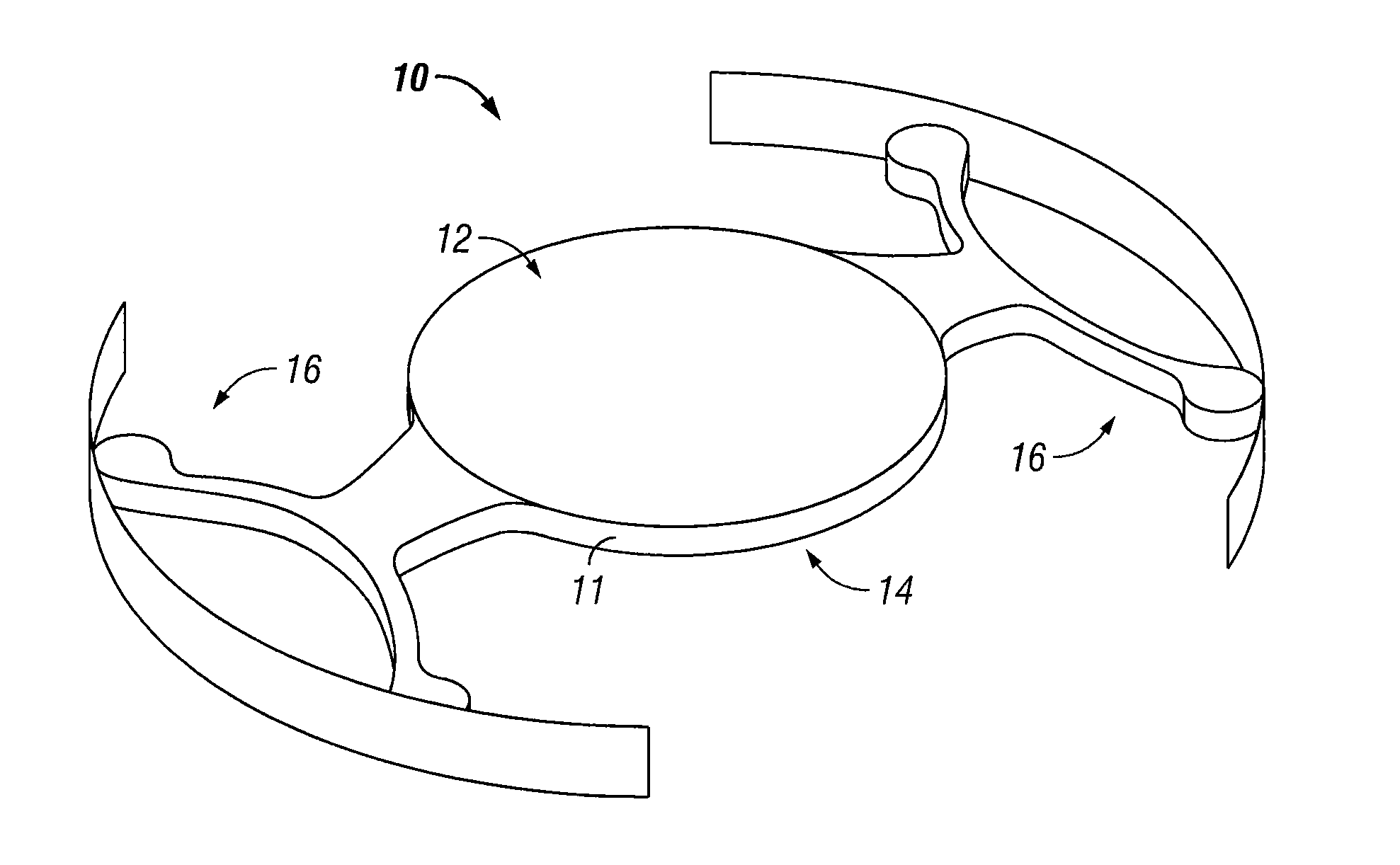
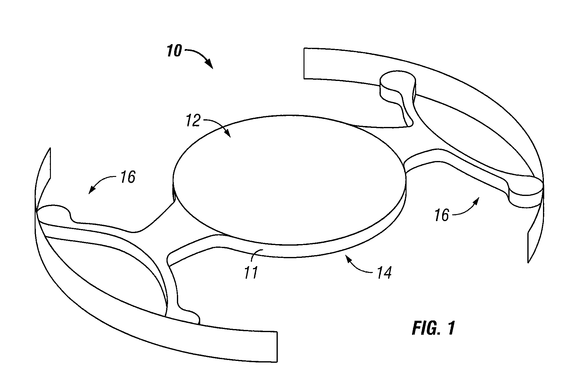
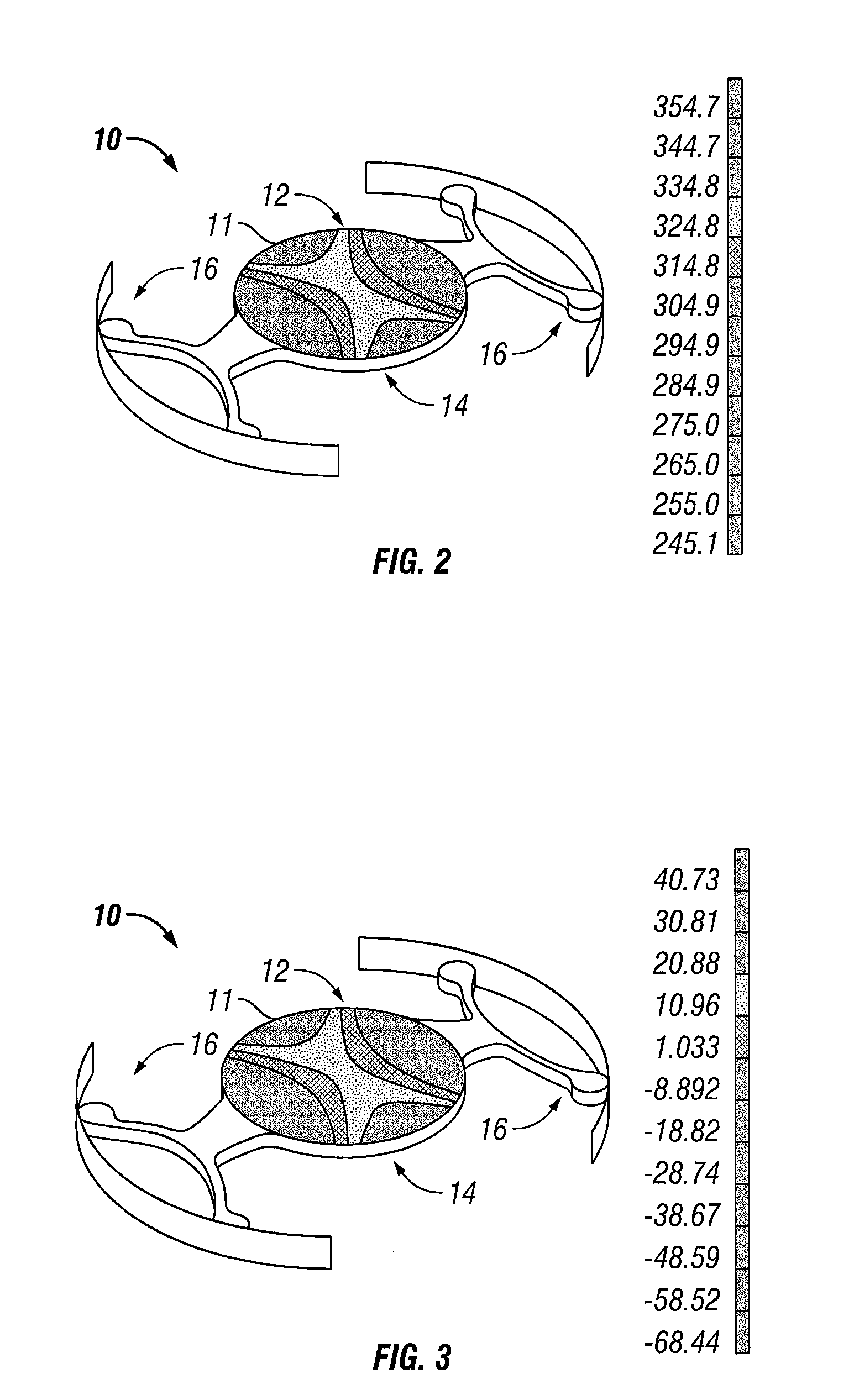
[0008]Traditional IOL designs have not considered the optical effect of the deformation induced by the mechanical elements that fixate the IOL in the eye. The deformation caused by compression may create aberrations (e.g., astigmatism, coma, etc) in the lens optic that can reduce the optical performance of the lens, especially at larger pupil diameters. The effects of optical surface deformation become more important as lens optics become more precise. Embodiments disclosed herein incorporate a lens optic designed with features, such as surface geometry, refractive index or other features for negating aberrations induced when the lens is in the eye. For example, the lens geometry can be selected geometry in an uncompressed state so that the lens has a desired geometry in a compressed state that is that reduces or eliminates the optical effects of compression in typical IOLs. As another example, the outer geometry of the lens can be selected so that the refractive index of the material is less than or greater the refractive index of the rest of the IOL to produce desired results when the IOL is implanted.)
[0010]An embodiment of an intraocular lens may include a lens optic and a pair of haptics coupled to the lens optic. The lens optic may have a first surface having a first surface uncompressed geometry in an uncompressed state and a second surface having a second surface uncompressed geometry in an uncompressed state. At least one of the first surface uncompressed geometry and the second surface uncompressed geometry may be formed such that the lens optic is substantially free of optical effects when in the compressed state. In some embodiments, the haptics define a first axis on the lens optic between the haptics and a second axis may be defined on the lens optic at some angle relative to the first axis. The uncompressed geometry of one or more of the first surface and the second surface relative to the first axis may differ from the compressed geometry of the first surface or the second surface about the second axis. The lens optic may have a thinner edge thickness where the edge intersects the second axis than where the edge intersects the first axis. In some embodiments, the uncompressed geometry of one or more of the first surface and the second surface is based on an anticipated compression of the lens optic due to the eye compartment or the haptics so that the lens optic compresses to a desired shape when implanted.
[0012]Additionally, the method can include creating one or more aberrations on one or more of the first surface and the second surface. The aberrations created in the intraocular lens when the lens is in an uncompressed state may offset the optical effects caused by the compression of the lens optic. In some embodiments, the aberration includes one of astigmatism, coma, or spherical aberration. In some embodiments, the aberration is formed to about 0.17 D at the spectacle place and being up to about 0.25 D at the intraocular lens plane. In some embodiments, the haptics define a first axis on the lens optic between the haptics, a second axis is defined at an angle relative to the first axis. The uncompressed geometry differs from the desired geometry about the second axis.
[0014]One advantage to creating a lens having a surface geometry based on an anticipated compressed state may be the ability to create thinner lenses. Thus, instead of making the lens optic thicker to reduce the effect of compression, or reduce the stiffness of the haptics, which could affect how well the IOL remains in place once implanted, embodiments disclosed herein can allow thinner lenses to be implanted without sacrificing optical performance.

Problems solved by technology

Traditional IOL designs have not considered the optical effect of the deformation induced by the mechanical elements that fixate the IOL in the eye.
The deformation caused by compression may create aberrations (e.g., astigmatism, coma, etc) in the lens optic that can reduce the optical performance of the lens, especially at larger pupil diameters.

Method used


Image

  • Intraocular lens configured to offset optical effects caused by optic deformation
  • Intraocular lens configured to offset optical effects caused by optic deformation
  • Intraocular lens configured to offset optical effects caused by optic deformation

Examples


Embodiment Construction

[0039]Embodiments of a method and apparatus for offsetting the optical effects caused by compression of the lens and deformation induced by compression of the lens optic or fixation components are disclosed.

[0040]Various embodiments of the disclosure are illustrated in the FIGURES, like numerals being generally used to refer to like and corresponding parts of the various drawings.

[0041]As used herein, the terms “comprises,”“comprising,”“includes,”“including,”“has,”“having” or any other variation thereof, are intended to cover a non-exclusive inclusion. For example, a process, article, or apparatus that comprises a list of elements is not necessarily limited to only those elements but may include other elements not expressly listed or inherent to such process, article, or apparatus. Further, unless expressly stated to the contrary, “or” refers to an inclusive or and not to an exclusive or. For example, a condition A or B is satisfied by any one of the following: A is true (or present...


PUM


Abstract

Intraocular lenses (IOLs) and related methods. One embodiment provides an IOL which includes a lens optic and a pair of haptics. The haptics can be coupled to the lens optic and can cause compression of the lens optic when the IOL is fixated in an eye. The lens optic can have a compressed geometry, an uncompressed geometry including an aberration, and a desired geometry. The compressed geometry can be the desired geometry. The aberration can be astigmatism, coma, or spherical aberration. For instance, the aberration can be astigmatism of about 0.17 D at the spectacle plane and of about 0.25 D at the intraocular lens plane. Moreover, the haptics can define a first axis between the haptics; the lens optic can define a second axis perpendicular to the first axis; and the uncompressed geometry can differ from the compressed geometry in the vicinity of the second axis.

Description

RELATED APPLICATIONS[0001]This application claims priority to U.S. provisional application Ser. No. 61 / 153,869, filed on Feb. 19, 2009, the contents which are incorporated herein by reference.TECHNICAL FIELD OF THE INVENTION[0002]The present invention relates to intraocular lenses. More particularly, the present invention relates to intraocular lenses with haptics and methods for offsetting the optical effects caused by optic deformation.BACKGROUND OF THE INVENTION[0003]The human eye is a generally spherical body defined by an outer wall called the sclera, having a transparent bulbous front portion called the cornea. The lens of the human eye is located within the generally spherical body, behind the cornea. The iris is located between the lens and the cornea, dividing the eye into an anterior chamber in front of the iris and a posterior chamber in back of the iris. A central opening in the iris, called the pupil, controls the amount of light that reaches the lens. Light is refracte...

Claims


Application Information

Patent Timeline
IPC IPC(8): A61F2/16
CPCA61F2/1616B29D11/023G02B27/0025A61F2/1637A61F2002/1699
Inventor STANLEY, DANIEL WALTERWENSRICH, DOUGLAS BRENTANGELOPOULOS, ROBERT DIMITRI
Owner ALCON RES LTD
Learn More