Combined motion sensor for use in feedback control systems for vibration isolation

a technology of motion sensor and feedback control system, which is applied in the field of active vibration isolation system, can solve the problems of inability to detect higher frequencies using the geophone itself, and mechanical rigidity

Active Publication Date: 2010-08-19
INTEGRATED DYNAMICS ENG
View PDF14 Cites 15 Cited by
  • Summary
  • Abstract
  • Description
  • Claims
  • Application Information

AI Technical Summary

Benefits of technology

[0007]The object of the present invention, therefore, is to provide an apparatus and a method for active vibration isolation which at least prevents the above-described disadvantages of the prior art.

Problems solved by technology

In addition to a support having the lowest possible mechanical rigidity, active vibration isolation systems have sensors and actuators which in a targeted manner counteract external vibrations which penetrate the system.
However, detection of higher frequencies using the geophone itself is not possible.

Method used


Image

  • Combined motion sensor for use in feedback control systems for vibration isolation
  • Combined motion sensor for use in feedback control systems for vibration isolation
  • Combined motion sensor for use in feedback control systems for vibration isolation

Examples


first embodiment

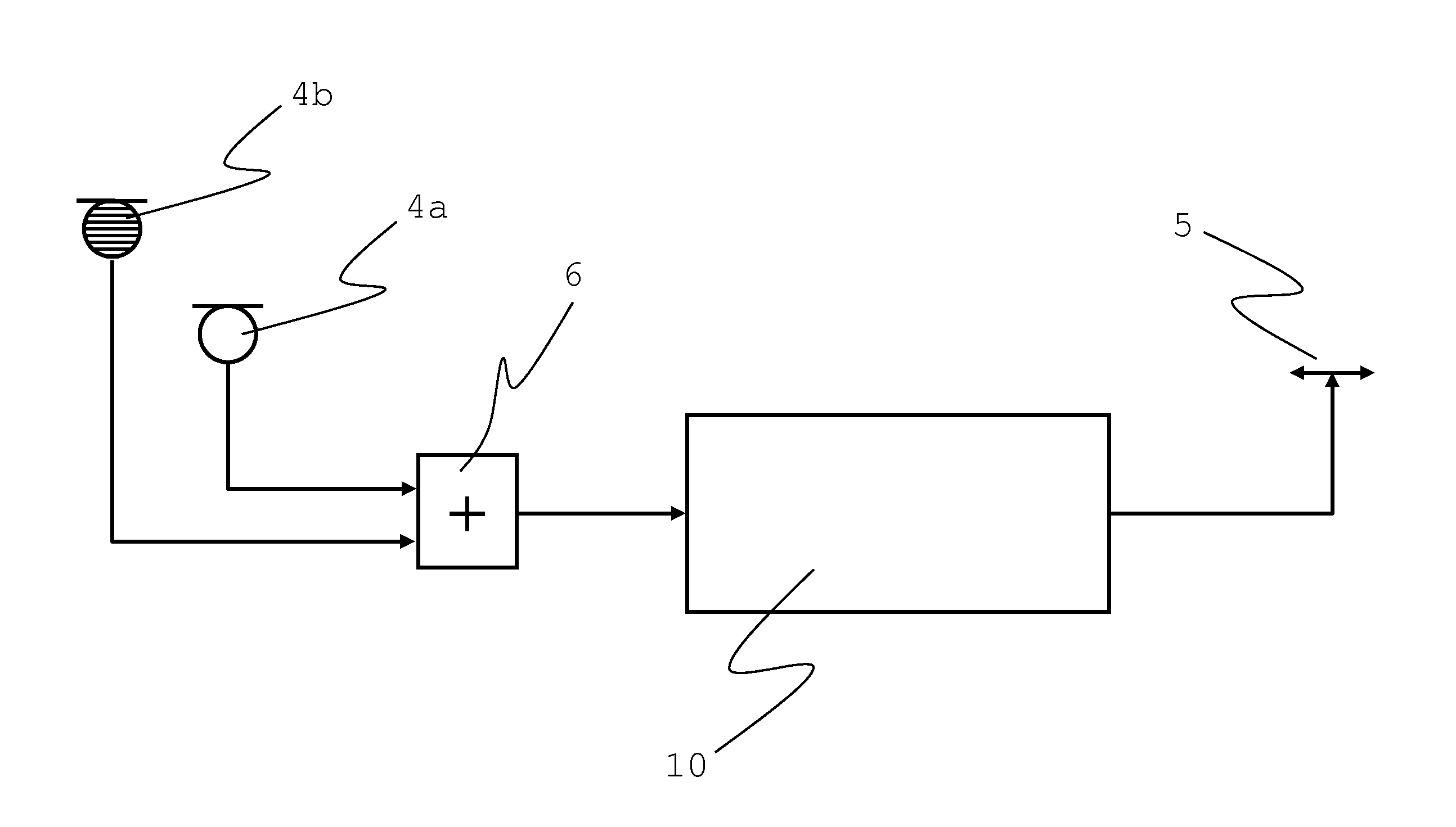
[0050]FIG. 3 shows a block diagram of a pair of sensors 4a and 4b in the invention. In this case, the respective sensor signals from the first acceleration sensor 4a and the second acceleration sensor 4b are combined or added before they are used in the feedback control 10. This is carried out in a means 6 for combination or addition. The two signals may be combined in a completely analog manner, in a completely digital manner, or in a mixed form. In this regard, either high-pass filters or low-pass filters are used to ensure that the overlapping signal portions are correctly added without increasing the amplitude, or use is made of the “frequency characteristic” of the sensors. Use is made of the “natural” high- and / or low-pass filter characteristic in order to perform the frequency division.

second embodiment

[0051]In contrast, FIG. 4 shows a block diagram of a pair of sensors 4a and 4b in the invention. In this embodiment, in each case an independent feedback control system 10a and 10b is used for the geophones 4a and the acceleration recorders 4b, respectively, and the combination 6 is performed only in the actuator signal. A first control device 10a is associated with the geophone as a first acceleration sensor 4a, and a second control device 10b is associated with the acceleration recorder as a second acceleration sensor 4b. In this manner a control system 10 from the prior art is doubled in a manner of speaking, and the supplemented second [acceleration sensor] is used to achieve high-frequency control by use of the acceleration recorders 4b. Combination of the control signals is necessary only in the actuator branch. In this regard it must be ensured that the respective signal components are not added in such a way as to increase the amplitude.

[0052]In summary, in two embodiments t...


PUM


Abstract

The present invention relates to a method for controlling a vibration isolation system, and an active vibration isolation system for vibration-isolated support of lithographic devices, wafer handling systems, and/or scanning microscopes. For this purpose the following are provided: a number of vibration transducers for supplying sensor signals which are representative of vibrations; a number of actuators for vibration compensation which may be controlled by supplying actuator control signals; a control device which is designed for processing the supplied sensor signals to form the actuator control signals, wherein the vibration transducers have at least one geophone sensor as a first acceleration sensor for detecting vibrations in a first frequency range, and at least one second acceleration sensor, which is different from the first acceleration sensor, for detecting vibrations in a second frequency range which extends the first frequency range.

Description

CROSS-REFERENCE TO RELATED APPLICATIONS[0001]The German patent application DE 10 2009 009 562.4, filed Feb. 19, 2009, is incorporated herein by reference.FIELD OF THE INVENTION[0002]The present invention relates to an active vibration isolation system for vibration-isolated support of lithographic devices, wafer handling systems, and / or microscopes, for example scanning microscopes.BACKGROUND OF THE INVENTION[0003]Vibration isolation systems are known, and are required in many technological sectors, for example in the semiconductor industry. DE 69817750 T2, for example, discloses a vibration isolation system which is provided in particular for vibration-isolated support of a lithographic device. A load to be supported, which typically includes a platform and components supported thereon, for example production equipment, is supported on air bearings.[0004]In addition to a support having the lowest possible mechanical rigidity, active vibration isolation systems have sensors and actu...

Claims


Application Information

Patent Timeline
Patent Type & Authority Applications(United States)
IPC IPC(8): G05D17/02
CPCF16F15/002G03F7/709G03F7/7085
Inventor HEILAND, PETER
Owner INTEGRATED DYNAMICS ENG
Why Eureka
Try Eureka