Road surface frictional coefficient estimating apparatus

a technology of friction coefficient and estimating apparatus, which is applied in the direction of braking system, structural/machine measurement, instruments, etc., can solve the problems of inconvenient updating of estimated value based on difference, low dependence between estimated value and detected value upon error of estimated value of and natural variation of actual lateral acceleration or longitudinal acceleration of the vehicle or the direction of yaw rate change velocity, etc., to achieve the effect of restricting deterioration

Active Publication Date: 2010-08-19
HONDA MOTOR CO LTD
View PDF9 Cites 14 Cited by
  • Summary
  • Abstract
  • Description
  • Claims
  • Application Information

AI Technical Summary

Benefits of technology

[0014]The present invention has been made in view of the background described above, and an object of the present invention is to provide a road surface frictional coefficient estimating apparatus capable of estimating the frictional coefficient of a road surface on which a vehicle is traveling while restraining an estimated value of the frictional coefficient from developing unstable changes and also restraining deterioration in the accuracy of the estimated value.

Problems solved by technology

Meanwhile, the direction of the actual lateral acceleration or longitudinal acceleration of the vehicle or the direction of the yaw rate change velocity naturally is not always fixed to a certain direction.
In such a case, it is highly likely that the difference between the estimated value and the detected value contains relatively many unwanted components that are not dependant upon an error of an estimated value of μ used to determine the estimated value.
Similarly, the technique disclosed in patent document 2 described above does not consider the polarities of the lateral acceleration and the longitudinal acceleration of the vehicle used for estimating μ.
Hence, according to the aforesaid techniques disclosed in patent documents 1 and 2, in the situation wherein the estimated value and the detected value of each of the lateral acceleration, the longitudinal acceleration and the yaw rate change velocity of the vehicle have polarities that are opposite to each other due to the influence of error components contained therein, the estimated value of μ may be inconveniently subjected to improper updating based on the difference.
In other words, there is an inconvenient case where the estimated value of μ is improperly updated on the basis of the difference in the situation wherein it is highly likely that the dependency of the difference between the estimated value and the detected value upon an error of an estimated value of μ is low.
Inconveniently, therefore, according to the techniques disclosed in patent documents 1 and 2, the estimated value of μ develops unstable changes, i.e., the estimated value diverges, or the accuracy of the estimated value deteriorates.
Further, the difference between the estimated value and the detected value of the lateral acceleration and the difference between the estimated value and the detected value of the yaw rate change velocity are also susceptible to an estimation error or the like of a side slip motional state amount of the vehicle in addition to an error of an estimated value of μ. For this reason, even if the estimated value of μ is updated on the basis of the aforesaid difference on the lateral acceleration or the aforesaid difference on the yaw rate change velocity, the error of the estimated value of μ may not be properly reflected.
In such a case, it is difficult to determine the estimated value of μ accurately and stably.
However, the techniques disclosed in patent documents 1 and 2 mentioned above do not take the aforesaid sensitivity into account.
This leads to a possibility that the estimated value of μ is undesirably updated unduly even when the sensitivity of the lateral acceleration, the longitudinal acceleration or the yaw rate change velocity in response to a change in μ is low.
As a result, the estimated value of μ inconveniently exhibits unstable changes or the accuracy of the estimated value of the μ undesirably deteriorates.

Method used


Image

  • Road surface frictional coefficient estimating apparatus
  • Road surface frictional coefficient estimating apparatus
  • Road surface frictional coefficient estimating apparatus

Examples


first embodiment

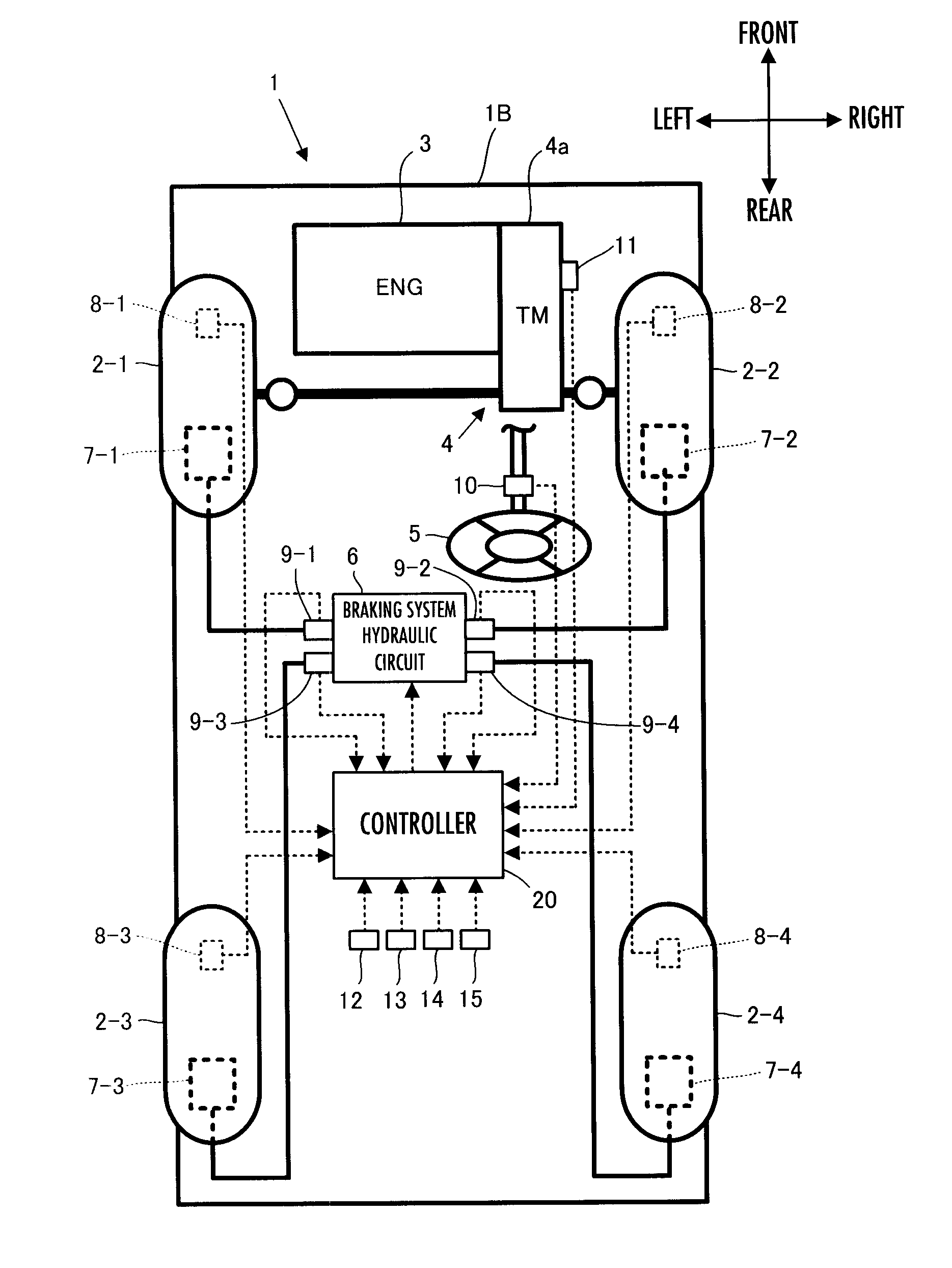
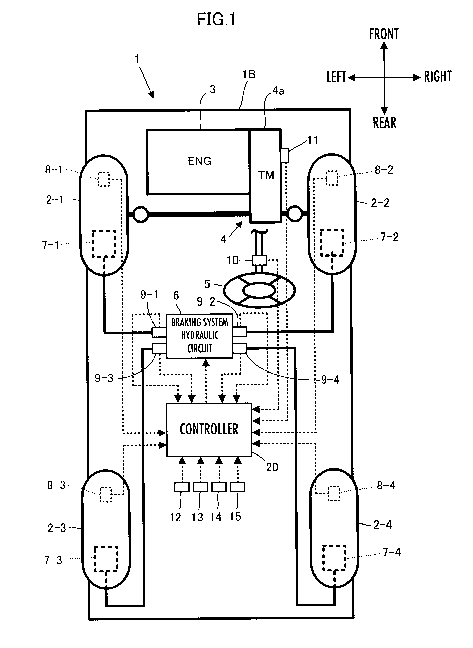
[0261]First, the processing by the controller 20 in a first embodiment will be described in detail. In the present embodiment, as illustrated by the block diagram of FIG. 3, the controller 20 has, as major functional means, an amount-to-be-observed detector 22, a vehicle model calculator 24, a μ estimator 26, a bank angle estimator 28, and a slope angle estimator 30.

[0262]The amount-to-be-observed detector 22 uses outputs from the aforesaid various sensors of the vehicle 1 (detection data) to carry out the processing for detecting predetermined types of amounts to be observed related to a behavior of the vehicle 1, and generates detected values of the amounts to be observed.

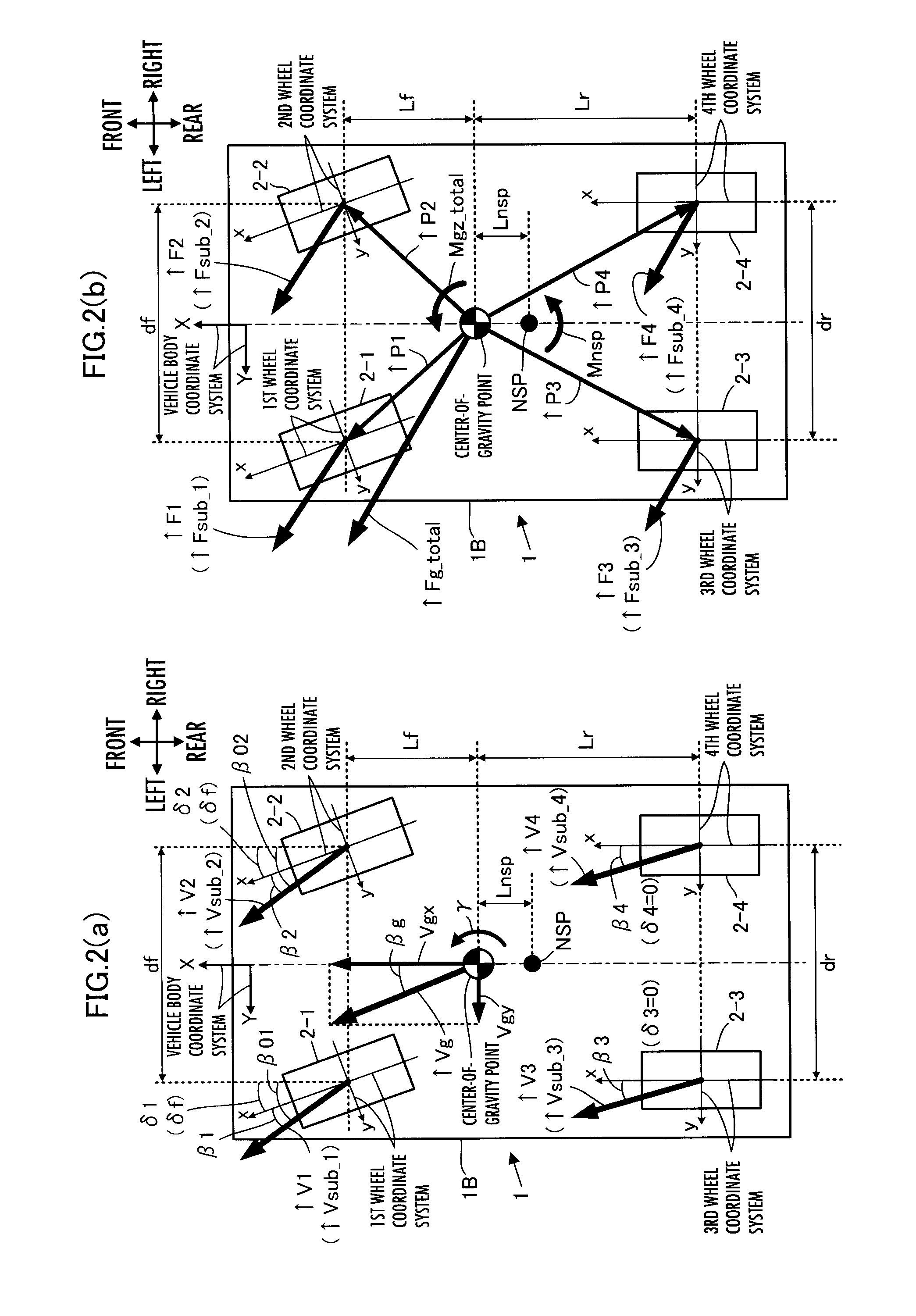
[0263]In the present embodiment, the amounts to be observed by the amount-to-be observed detector 22 include actual steering angles δ1_act and δ2_act of steering control wheels (front wheels) 2-1 and 2-2, an actual wheel speed Vw_i_act (i=1, 2, 3, 4), an actual yaw rate γ_act and an actual yaw angular acceleratio...

second embodiment

[0605]A second embodiment of the present invention will now be described with reference to FIG. 14 and FIG. 15. The present embodiment differs from the aforesaid first embodiment only in the method for setting the gain adjustment parameter Kmu_att in a frictional coefficient increasing / decreasing manipulated variable determiner 26e.

[0606]In the first embodiment described above, Kmu_att has always been set to 1 in the case where the determination result in S122-5-1 is affirmative, i.e., the updating cancellation condition does not apply. In contrast thereto, according to the present embodiment, Kmu_att is set such that Kmu_att changes within a range from 0 to 1 according to Mnsp_estm and Mnsp_sens as illustrated in, for example, FIG. 14 in the case where the determination result in S122-5-1 is affirmative.

[0607]FIG. 14 visually illustrates the set values of Kmu_att corresponding to pairs of the values of Mnsp_estm and the values of Mnsp_sens on a coordinate plane, Mnsp_estm being on...

third embodiment

[0629]A third embodiment of the present invention will now be described with reference to FIG. 16. The present embodiment differs from the aforesaid second embodiment only in the method for setting the gain adjustment parameter Kmu_att in the frictional coefficient increasing / decreasing manipulated variable determiner 26e.

[0630]More specifically, the present embodiment considers not only the polarities of an NSP yaw moment estimated value Mnsp_estm and an NSP yaw moment detected value Mnsp_sens but also the polarity of a μ sensitivity p (γ_sens, δf_sens, Vgx_estm). Further, if a predetermined updating cancellation condition including at least a condition related to the polarities applied, then updating of the road surface frictional coefficient estimated value μ_estm according to a yaw moment estimation error Mnsp_err is cancelled.

[0631]Here, as is obvious from the aforesaid expression 4-13b, the μ sensitivity p indicative of the ratio of an increment of an actual NSP yaw moment Mn...


PUM


Abstract

A road surface frictional coefficient estimating apparatus includes a device which determines a first estimated value of a to-be-compared external force acting on a vehicle due to the resultant force of road surface reaction forces by using a determined frictional coefficient estimated value and the like, and a device which determines a second estimated value of the to-be-compared external force from the observed value of motional state amounts of the vehicle that define an inertial force corresponding to the to-be-compared external force. The estimated value of a road surface frictional coefficient is updated on the basis of the difference between the first estimated value and the second estimated value. In the case where the first estimated value and the second estimated value have polarities that are opposite from each other, the updating of the estimated value of the road surface frictional coefficient on the basis of the difference is not carried out.

Description

BACKGROUND OF THE INVENTION[0001]1. Field of the Invention[0002]The present invention relates to a road surface frictional coefficient estimating apparatus which estimates the frictional coefficient of a road surface on which a vehicle is traveling.[0003]2. Description of the Related Art[0004]As techniques for estimating the frictional coefficient (hereinafter referred to simply as “μ” in some cases) of a road surface on which a vehicle is traveling, the techniques disclosed in, for example, Patent Publication No. 3669668 (hereinafter referred to as “patent document 1”) and Japanese Patent Application Laid-Open No. 2003-118554 (hereinafter referred to as “patent document 2”) have been proposed by the present applicant.[0005]According to the technique disclosed in patent document 1, a road surface reaction force acting on each wheel from a road surface (a cornering force (a lateral force of a vehicle) and a braking / driving force (a longitudinal force of the vehicle)) is estimated usi...

Claims


Application Information

Patent Timeline
Patent Type & Authority Applications(United States)
IPC IPC(8): G06F7/00B60W40/06
CPCB60T8/172B60T2210/12B60T2230/02B60W40/068
Inventor TAKENAKA, TORUMORI, YOSHIHIROURABE, HIROYUKI
Owner HONDA MOTOR CO LTD
Why Eureka
Try Eureka