Solar thermal power plants

Inactive Publication Date: 2010-08-26
SIEMENS CONCENTRATED SOLAR POWER
View PDF12 Cites 29 Cited by
  • Summary
  • Abstract
  • Description
  • Claims
  • Application Information

AI Technical Summary

Benefits of technology

[0039]efficiency is increased significantly, and cost

Problems solved by technology

Although the steam-electric cycle is more efficient at high temperatures, at a particular high temperature threshold, some thermal fluids may dissociate or otherwise break down or become less effective at tran

Method used


Image

  • Solar thermal power plants
  • Solar thermal power plants
  • Solar thermal power plants

Examples


first embodiment

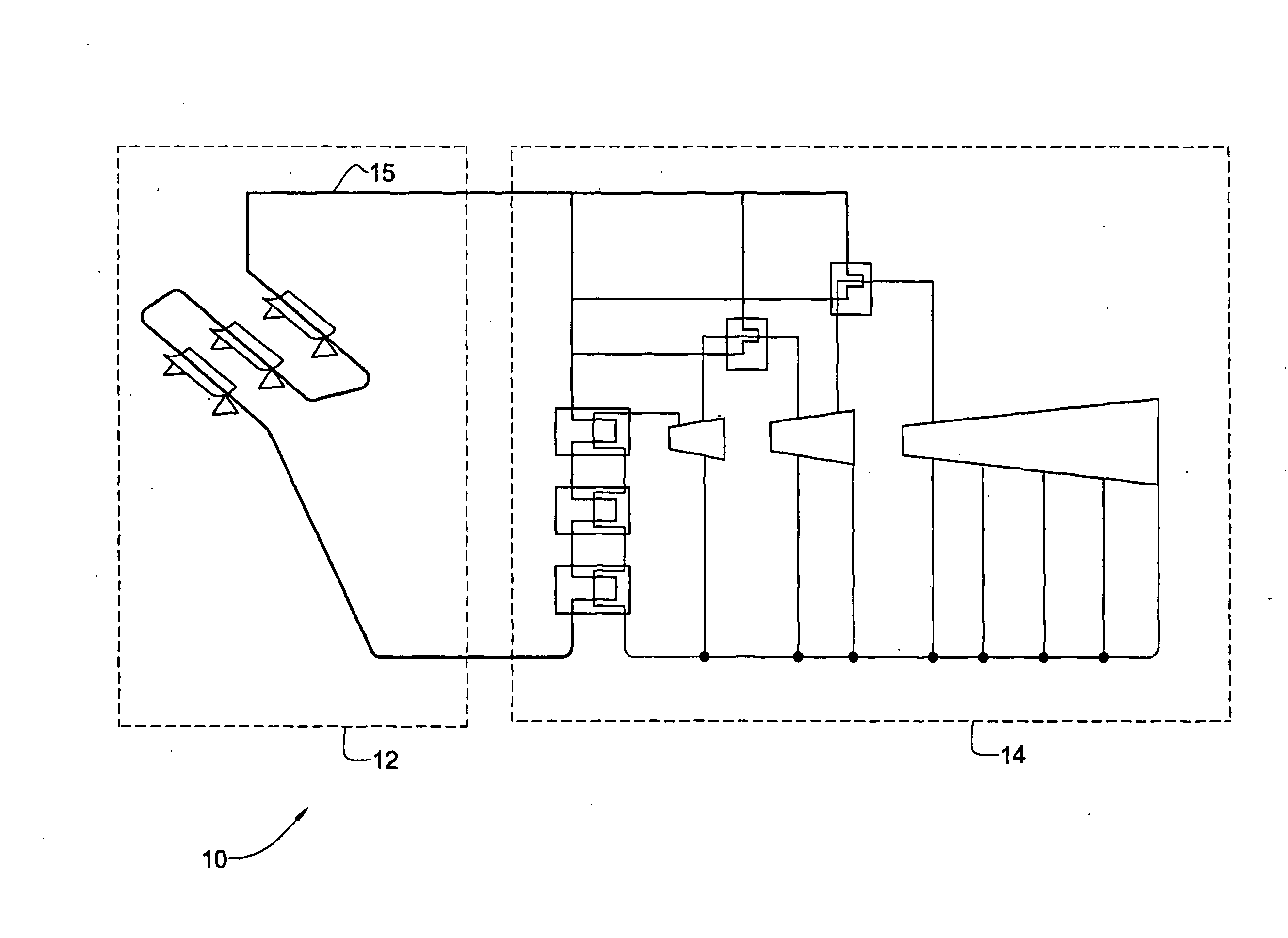
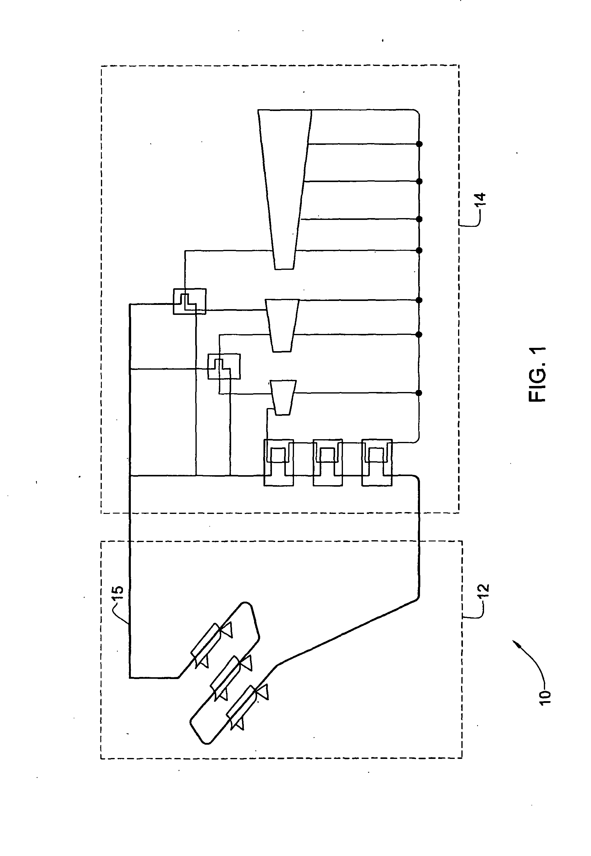
[0049]As illustrated schematically in FIG. 1, there is provided a solar thermal power plant, which is generally indicated at 10, according to the present invention. The plant 10 comprises a solar collection system 12 and a steam-electric power plant 14. The plant further comprises a heating circuit 13, which comprises one or more tube radiation absorbers 15 (which also constitute a portion of the solar collection system 12).

[0050]The solar collection system 12 comprises one or more tube radiation absorbers 15 and a plurality of trough collectors 17, such as single-axis parabolic reflectors. Alternatively, any suitable means for concentrating solar radiation, such as Fresnel collectors, may be provided. The tubes, including those which are not exposed to solar radiation, constitute a heating circuit of the plant 10. The tube radiation absorbers contain a thermal fluid therein, such as oil (phenyls) which are commercially available, such as under the trade name Therminol® VP-1. Accord...

second embodiment

[0076]The second embodiment may also comprise other features and / or advantages. For example, if one of the solar collection systems 12a, 12b, 12c, needs to be shut down, for example due to malfunction or maintenance, it may be possible for the associated turbine to be shut down, and to provide a bypass flow channel to channel the working fluid between the two remaining turbine, and thus permit operation of the plant 10 using these two turbines, albeit at a lower efficiency. Since there are no fuel related running costs for the solar collection systems, it may still be worthwhile to run the plant at the lower efficiency temporarily.

[0077]Optionally, any two or all of the solar collection systems 12a, 12b, 12c, may be interconnected by means of suitable conduits and valves to enable the same to be in selective fluid communication when desired, in any desired combination, and thus enable thermal fluid to be exchanged between them so that they may operate effectively in a similar manner...


PUM


Abstract

A solar thermal power plant is provided comprising a solar collection system and a steam-electric power plant. The solar collection system comprises one or more tube radiation absorbers containing a thermal fluid therewithin, the system being configured to heat the thermal fluid by passing the thermal fluid through the one or more tube radiation absorbers while the absorbers are irradiated with solar radiation. The steam-electric power plant comprises an intermediate-pressure steam turbine, a low-pressure steam turbine, at least one additional steam turbine having an inlet pressure higher than that of the intermediate-pressure steam turbine, and piping containing a working fluid. Each turbine is associated with a heat exchange system adapted to transfer heat from the thermal fluid to the working fluid.

Description

FIELD OF THE INVENTION[0001]This invention relates to solar thermal power plants, and in particular, to solar thermal power plants which provide thermal energy to steam-electric power generating plants.BACKGROUND OF THE INVENTION[0002]Amid concerns over global warming, and forecasts of both the depletion of non-renewable energy sources and rising power demand, suppliers of energy are increasingly seeking alternative primary sources of energy. One such source of energy is solar energy, and one way of utilizing solar energy is with a solar thermal power plant.[0003]One type of solar power plant utilizes a “radiation concentrator collector” which concentrates the solar radiation by focusing it onto a smaller area, e.g., using mirrored surfaces or lenses. In this system, a reflector, which is typically parabolic, receives and reflects (focuses) incoming solar radiation onto a radiation absorber, which is formed as a tube. The tube radiation absorber is concentrically surrounded by a tre...

Claims


Application Information

Patent Timeline
IPC IPC(8): F03G6/06F03G6/00
CPCF01K7/22Y02E10/46F03G6/067F01K25/08
Inventor SCHAAL, MICHAEL
Owner SIEMENS CONCENTRATED SOLAR POWER
Why Eureka
Try Eureka