
Method and apparatus for pipe testing

Active Publication Date: 2010-08-26
VERDERG PIPE TECH LTD
View PDF17 Cites 19 Cited by
  • Summary
  • Abstract
  • Description
  • Claims
  • Application Information

AI Technical Summary

Benefits of technology

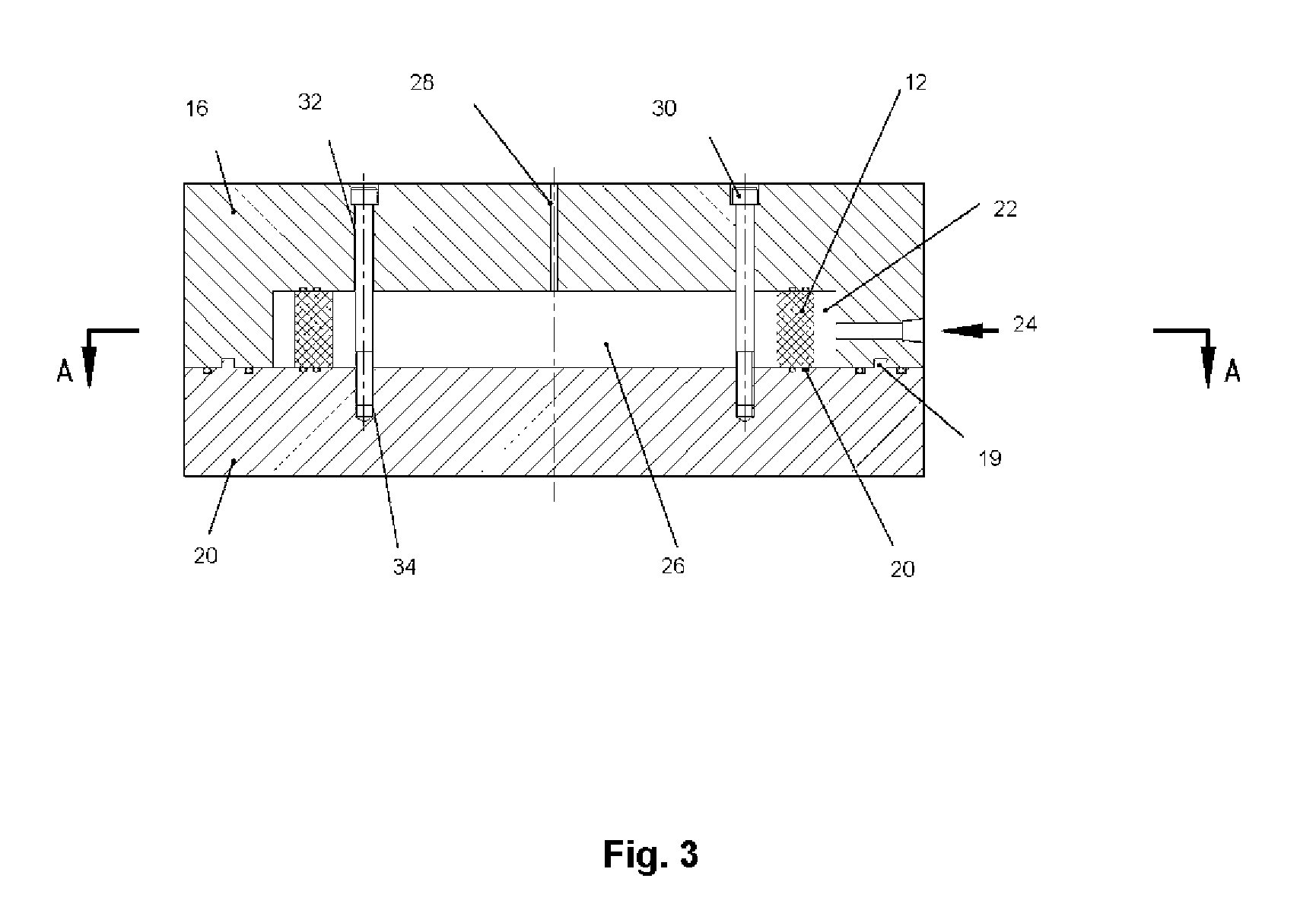
[0030]The first and second sections can include inter-engaging formations such as spigots and recesses, to allow accurate location of one against the other when forming the chamber.
[0038]providing the basis for optimising the wall thickness of pipes intended for installation at specific depths and with specific equipment thus allowing cost reduction to be realised; and

Problems solved by technology

A major risk experienced during the installation of these deep-water pipelines is from the pressure applied by the water causing the pipe to deform out of its initial round shape and deform into an almost flat configuration.
This is called external pressure collapse and if not controlled can result in the total loss of the pipeline.
However, the consequences of external pressure collapse buckling are so great that these theoretical studies are not sufficient for confident management of the risk.
Also, the most important method for reducing the potential for such local collapse, by increasing the wall thickness of the pipe, is so expensive and possibly not technically realisable, that the proposed pipeline might well not be commercially feasible.
This in turn raises the possibility that the exploitation of the gas or oil reservoirs are abandoned.
Only one or two laboratories have such facilities available and the tests are very expensive, in the order of $100,000 for one test.
However, the factors are based on the few previous available tests; the possibility of carrying out such tests on complete pipe joints during fabrication of the pipe are not realistic since the tests take a significant time to be set up and completed.
It is therefore axiomatic that a long deep-water pipeline is more vulnerable to collapse than a short deep-water pipeline purely because there is a greater statistical probability in a long line of a single joint manufactured sufficiently out-of-specification to precipitate collapse.

Method used


Image

  • Method and apparatus for pipe testing
  • Method and apparatus for pipe testing
  • Method and apparatus for pipe testing

Examples


Embodiment Construction

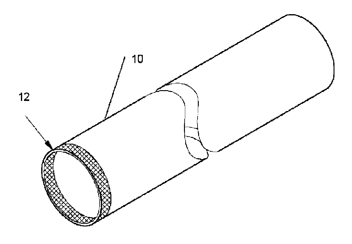
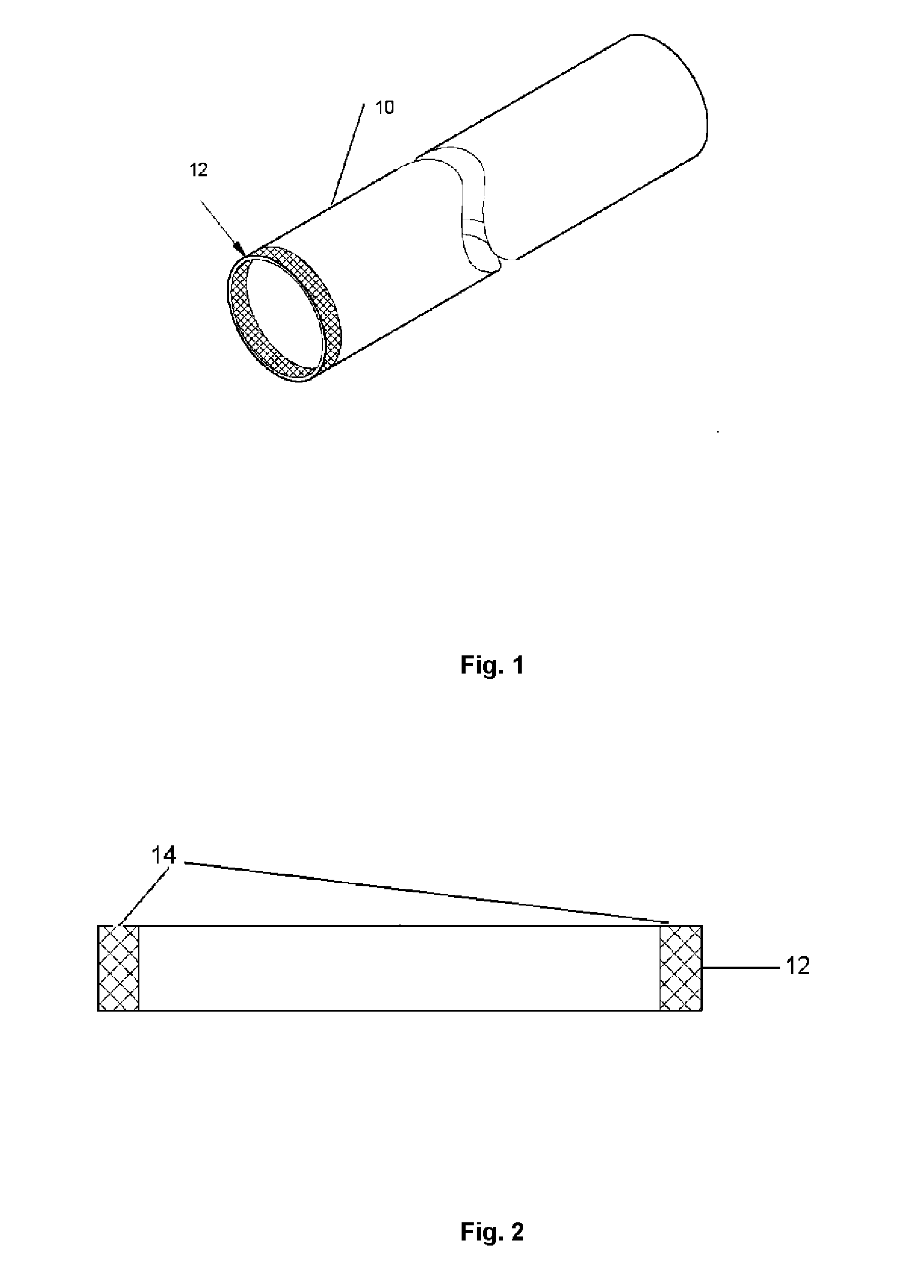
[0045]Tests on long sections of individual pipe joints have shown that the deformations that lead to external collapse are uniform along the pipe. This observation is supported by theoretical studies and numerical modelling. The implication is that the occurrence of external pressure collapse will be the same for a ring cut from the pipe as for the complete joint length of pipe that is subjected purely to external pressure. The testing approach of the invention is therefore is based on cutting short sections from a pipe and machining the ring to a uniform length. The ring is placed in a rigid frame that allows the machined faces of the ring to be sealed such that a pressure can be applied only to the outer circular surface of the ring. The inner circular surface of the ring is maintained at ambient pressure and thus is suitable for attachment of devices to measure the strains and deformations that are caused by the pressure on the outer circular surface of the ring.

[0046]The seals o...


PUM


Abstract

A method of testing pipes for use in making subsea pipelines comprises cutting a ring from one or more pipes of the type used to make the pipeline; forming flat, substantially parallel surfaces on the ends of the ring; providing means for measuring strain and deformation of the ring; mounting the ring in a pressure chamber such that the ends of the ring form seals with opposing walls of the chamber to isolate the inside of the ring from the outside; increasing the pressure outside the ring and measuring the strain and deformation on the ring as the pressure increases; and using the deformation and strain measurements to determine a wall thickness for pipes to be used for the pipeline. An apparatus for testing rings cut from pipes for use in making subsea pipelines, comprises first and second test chamber sections which, when placed together define a test chamber for receiving the ring to be tested; one or more sensors for measuring strain and deformation of the ring; sealing means located in the chamber for forming a seal against the ring when received in the chamber; means for clamping the first and second sections together to form the chamber and engage the sealing means against the ring when received in the chamber to form a pressure resistant seal between the inside and outside of the ring; and a fluid inlet port in one of the chamber sections to allow a pressurised fluid to be admitted to the chamber outside the ring when received in the chamber.

Description

TECHNICAL FIELD [0001]This invention relates to methods and apparatus for testing pipes such as those used for forming underwater pipelines.BACKGROUND ART [0002]There has been a progressive development of very deepwater reservoirs of gas and / or oil around the world. Until about 10 years ago, very deep water was defined to be any depth greater than about 1000 m. Currently however, so many pipelines have been installed in depths greater than this that the definition of very deep water is currently about 2000 m. This development in installation capability is continuing and currently pipelines in 3500 m water depth are being planned.[0003]The pipelines are typically installed empty, i.e. filled with air at ambient pressure and only filled with oil or gas under pressure once installation is completed. A major risk experienced during the installation of these deep-water pipelines is from the pressure applied by the water causing the pipe to deform out of its initial round shape and deform...

Claims


Application Information

Patent Timeline
IPC IPC(8): G01B5/06
CPCG01N2203/0274G01N3/12F16L55/00G01N3/10
Inventor ROBERTS, PETER MILESWALKER, ALASTAIR CHALMERS
Owner VERDERG PIPE TECH LTD
Learn More