Thermal energy storage device

a technology of energy storage device and thermal energy, which is applied in the direction of solar heat storage, machines/engines, light and heating equipment, etc., can solve the problems of low efficiency, high cost, and inability to achieve significant commercialization

Inactive Publication Date: 2010-08-26
RICOR GENERATION
View PDF45 Cites 51 Cited by
  • Summary
  • Abstract
  • Description
  • Claims
  • Application Information

AI Technical Summary

Problems solved by technology

Philips, its licensees and others developed many versions of Stirling engines and coolers aimed at a wide range of applications, but outside of a few cryocooler applications, no significant commercialization has occurred.
The primary reasons are the inherent life and reliability limitations imposed by the sliding seal in all kinematic Stirling machines (where piston and displacer motions are constrained by conventional crankshafts and related mechanisms), and the high cost that results from no engines having crossed the threshold from demonstration machines to high level production of an engine with comprehensive design for manufacture and assembly (“DFMA”).
Single acting alpha engines can only be implemented as kinematic ...

Method used


Image

  • Thermal energy storage device
  • Thermal energy storage device
  • Thermal energy storage device

Examples


Embodiment Construction

Overview

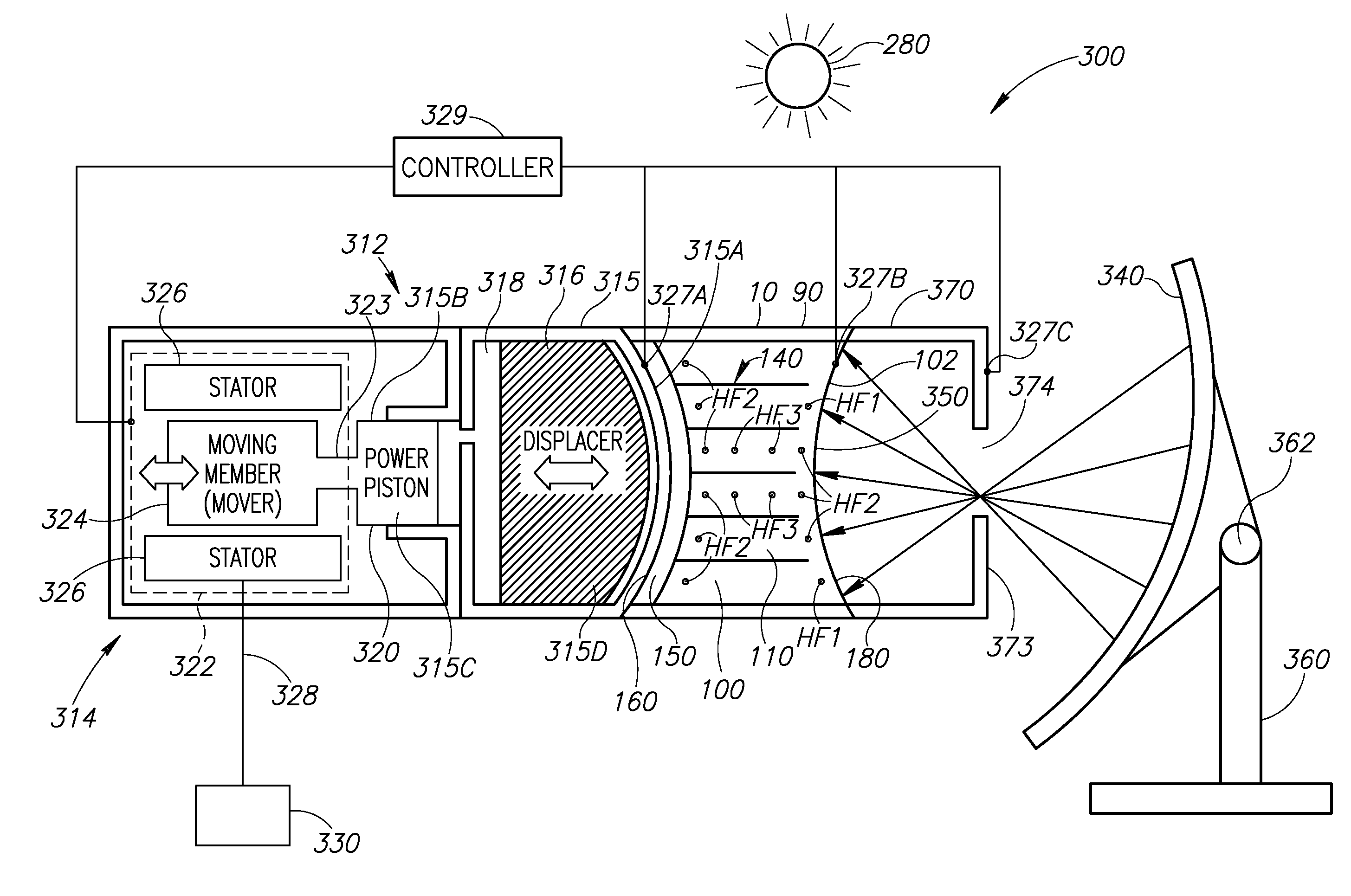
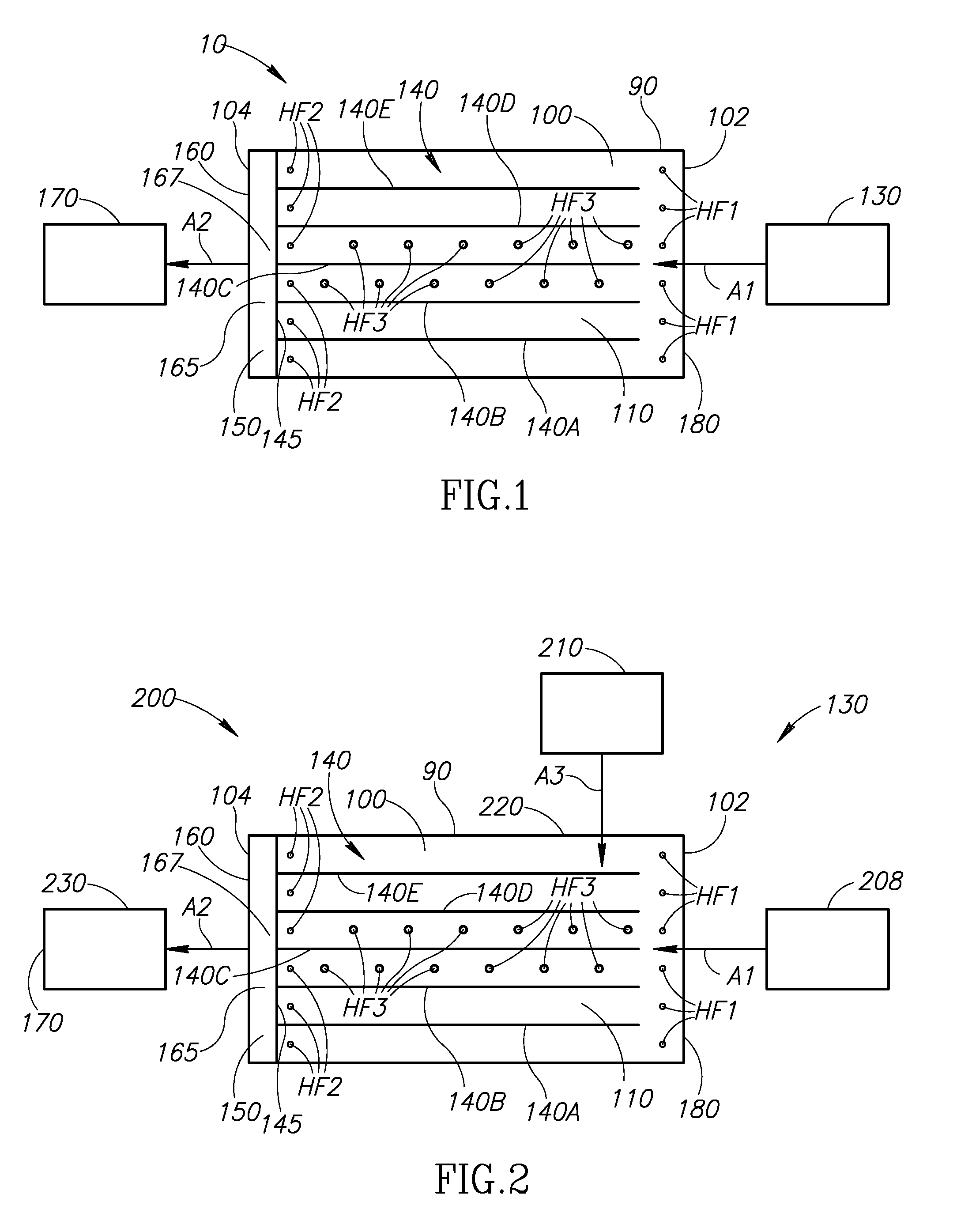
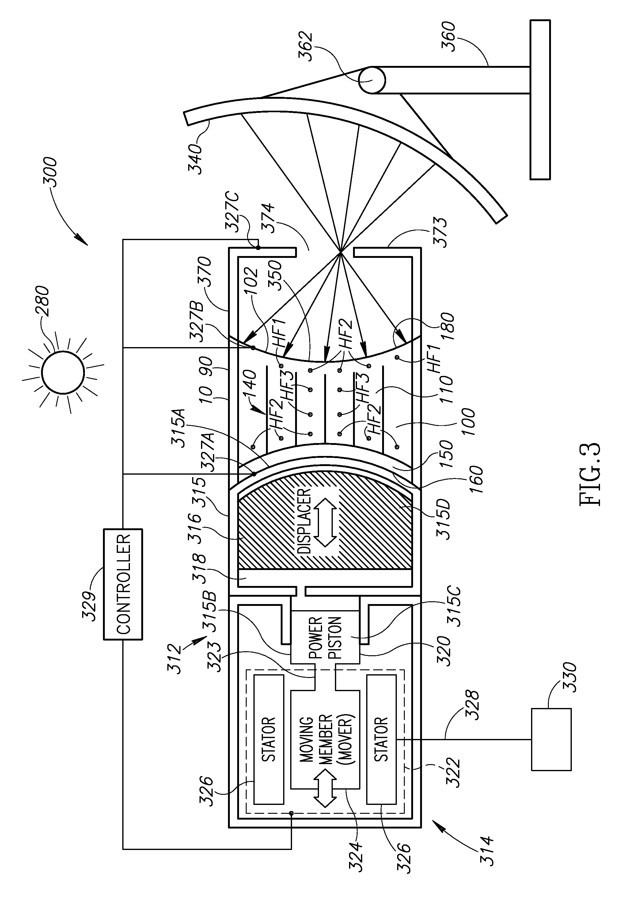
[0040]The present application provides a thermal energy storage (“TES”) and transfer device for storing thermal energy generated by a thermal energy source and transferring it to a different physical location. The stored thermal energy may be used at a later time by a recipient structure or device such as a thermal energy driven power generation device or any other device requiring thermal energy (e.g., a Stirling engine or a steam turbine). The TES device may be described as a buffering means for thermal energy supplied by a thermal energy source before the thermal energy is provided to the recipient structure or device. Thus, the TES device may be used to introduce a delay period between the generation of the thermal energy and its consumption by a thermal energy driven power generation device. Alternatively, the TES device may be configured to provide thermal energy to a thermal energy driven power generation device without introducing a delay. As will be described below,...


PUM


Abstract

A thermal energy storage (“TES”) device including a vessel housing a continuous volume of a TES media, an input portion, an output portion, and a plurality of thermal energy transport members connected to the input portion and/or the output portion. The input portion receives thermal energy from a thermal energy source. The received thermal energy is transported by one or more of the thermal energy transport members to the output portion and/or the TES media for storage. One or more of the thermal energy transport members connected to the output portion transport stored thermal energy from the TES media to the output portion. The output portion is coupled to an external device, such as a Stirling engine, and configured to transfer thermal energy the external device. Optionally, selected ones of the thermal energy transport members connected to both the input and output portions may be insulated from the TES media.

Description

CROSS REFERENCE TO RELATED APPLICATION(S)[0001]The present application claims the benefit of U.S. Provisional Patent Application No. 61 / 079,787, filed Jul. 10, 2008, which is incorporated herein by reference in its entirety.STATEMENT REGARDING FEDERALLY SPONSORED RESEARCH OR DEVELOPMENT[0002]The invention described herein was made under federally sponsored research and development with Department of the Navy contract no. N00014-07-M-0409 and may be manufactured and used by or for the United States Government for governmental purposes without the payment of any royalties thereon.BACKGROUND OF THE INVENTION[0003]1. Field Of The Invention[0004]The present invention is directed generally to thermal energy storage devices.[0005]2. Description of the Related Art[0006]The Stirling engine was first described in an 1816 patent issued to a Scottish clergyman named Robert Stirling. Many variants of the Stirling cycle were implemented over the next century and applied to applications such as pu...

Claims


Application Information

Patent Timeline
IPC IPC(8): F24J2/34F28D20/00F24S90/00
CPCF03G6/06F24J2/34F24J2/42F28D2020/0047Y02E10/46Y02E60/145F28D20/02F24S90/00F24S20/20F24S60/10Y02E60/14Y02E10/40F03G6/068
Inventor QIU, SONGGANGWHITE, MAURICE A.YARGER, DAVID J.GALBRAITH, ROSS
Owner RICOR GENERATION
Why Eureka
Try Eureka