
Running and Cement Tubing

a cement tubing and running technology, applied in the field of running and cement tubing, can solve the problems of difficult to apply the torque necessary to rotate the string from the surface, and the friction between the string and the bore wall is difficult to reduce. the effect of friction

Active Publication Date: 2010-08-26
GRANT PRIDECO LP
View PDF40 Cites 32 Cited by
  • Summary
  • Abstract
  • Description
  • Claims
  • Application Information

AI Technical Summary

Benefits of technology

[0008]According to a first aspect of the present invention there is provided a method of running a bore-lining tubing string into a bore, the method comprising running a tubing string into a bore while agitating the string to reduce the friction between the string and the bore wall.
[0011]The tubing string may be translated solely axially, or may also be rotated as it is advanced into the bore. In both cases the agitation of the string has been found to reduce the drag experienced by the string.
[0012]In some cases, the string may be provided with a drill bit, reaming shoe or other cutting structure tool at its leading end, primarily to remove or displace bore obstructions which would otherwise impede the progress of the tubing string through the bore. The rotation of the drill bit may be provided by means of a downhole motor or by rotation from surface. As noted above, agitation of the string facilitates axial and rotational movement of the string in the bore and also allows for more effective transfer of weight to the drill bit: testing has demonstrated that, without agitation, typically only 10% of the weight applied to a tubing string at surface is transferred to the string nose, whereas with appropriate agitation 90% of the applied weight may be available at the nose, providing for far more effective cutting or reaming of bore obstructions.
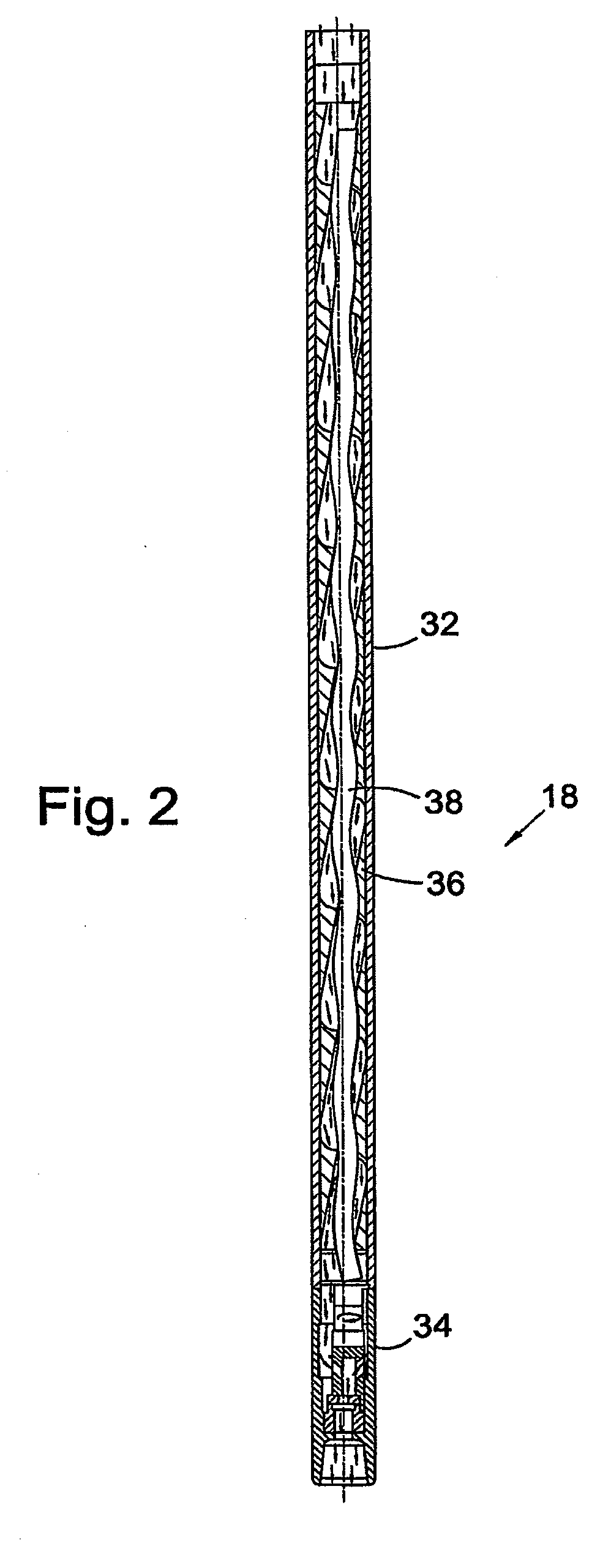
[0014]Preferably, the agitator is fluid actuated, and in particular may be actuated by fluid which is pumped through the tubing string. The actuating fluid may be conventional drilling fluid or “mud” or may be cement slurry or treating fluid. In a preferred embodiment the agitator is adapted to be actuated by both drilling fluid and cement slurry. Preferably, the fluid acts on a downhole motor, most preferably a positive displacement motor. This offers the advantage that the speed of the motor, and thus the rate of agitation, may be controlled by varying the fluid flow rate. Thus, the agitation frequency may be selected to suit local conditions and parameters, for example to match or to avoid a natural frequency of the string assembly.
[0018]In preferred embodiments, the operation of the agitator will thus continue to agitate the tubing string and will also apply pressure pulses to the cement as it flows into and through the annulus. The agitation of the string will facilitate movement or manipulation of the tubing string. This movement is believed to facilitate displacement of fluid and other deposits from the annulus and ensure uniform distribution of the cement through and around the annulus. In other embodiments the movement of the tubing string induced by the agitation of the string may be sufficient to provide a similar effect. It is also believed that the application of pressure pulses to the cement, preferably negative pressure pulses in contrast to the positive pressure pulses experienced above the agitator, and the pulsed advancement of the cement slurry through the annulus, will also assist in displacing material from the annulus ahead of the cement and in breaking up or dislodging any deposits in the annulus. It is also believed that the pressure pulses assist in maintaining the cement in a fluid state before setting commences and thus facilitate flow of the cement into and through the annulus.
[0021]The ability to vary one or more of the agitation frequency and the amplitude of the pressure pulses allows the agitator to be driven at a rate suitable for cementing, which may be different from the rate best suited to running the tubing string into the bore.

Problems solved by technology

The outer diameter of the strings will be only slightly less than the bore inner diameter and thus, particularly in extended reach and highly deviated bores, there may be considerable friction between the string and the bore tending to resist movement of the string through the bore.
However, it may prove difficult to apply torque from surface to rotate such a shoe, as the connectors between adjacent sections of the string are generally not capable of withstanding any significant torque.
This may be facilitated by rotating the string as the cement is pumped into the annulus, however as noted above it may be difficult to apply the torque necessary to rotate the string from surface, due to the frictional forces acting between the string and the bore wall.

Method used


Image

  • Running and Cement Tubing
  • Running and Cement Tubing
  • Running and Cement Tubing

Examples


Embodiment Construction

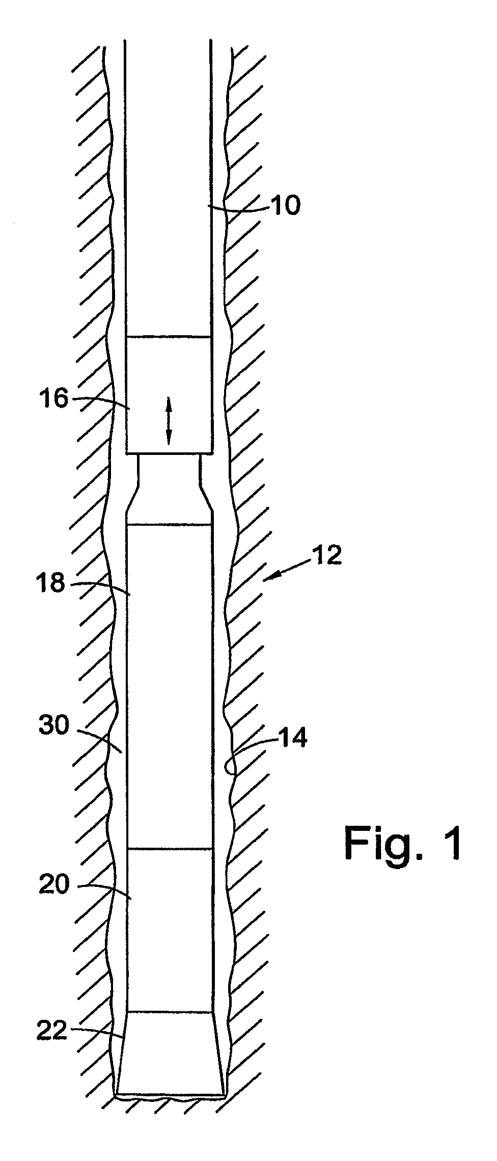
[0028]Reference is first made to FIG. 1 of the drawings, which illustrates the leading end of a string of bore-lining tubing 10 incorporating apparatus 12 in accordance with an embodiment of the present invention. In particular, the tubing is in the form of liner 10 intended to form the last lined section of a drilled bore 14 which has been drilled from surface to intersect a hydrocarbon-bearing formation. In this embodiment the liner has a solid wall, but other embodiments of the invention may involve use of slotted or otherwise perforated tubing.

[0029]The apparatus 12 comprises a shock sub 16, an agitator 18, a downhole motor 20 and a drill bit 22 and, as will be described, is used to facilitate running the liner string 10 into the bore 14 and then cementing the liner string 10 in the bore.

[0030]The drill bit 22 and downhole motor 20 are substantially conventional and are used in this embodiment to clear obstructions from the bore 14 as the string 10 is advanced through the bore. ...


PUM


Abstract

A method of running a bore-lining tubing string into a bore includes running a tubing string, typically a liner string, into a bore while agitating the string. The agitation of the string reduces the friction between the string and the bore wall and thus facilitates the translation of the string into the bore. The agitation may also take place while the tubing is being cemented in the bore. Pressure pulses may be applied to fluid in the bore, which fluid may be cement slurry.

Description

CROSS-REFERENCE TO RELATED APPLICATIONS[0001]This application is a continuation of prior U.S. application Ser. No. 10 / 576,884, filed Mar. 29, 2007, which was the National Stage filing under 35 U.S.C. 371 of International Application No. PCT / GB2004 / 004503, filed Oct. 25, 2004, which International Application was published by the International Bureau in English on May 12, 2005 and which International Application claims priority to United Kingdom Application No. GB 0324744.2, filed on Oct. 23, 2003, all of which are hereby incorporated by reference herein in their entirety.FIELD OF THE INVENTION[0002]This invention relates to apparatus and methods for use in running tubing strings into drilled bores. Aspects of the invention also relate to cementing tubing in drilled bores.BACKGROUND OF THE INVENTION[0003]Bores drilled to access subterranean formations, and in particular hydrocarbon-bearing formations, are typically lined with metallic tubing, known as casing or liner. After the tubing...

Claims


Application Information

Patent Timeline
Patent Type & Authority Applications(United States)
IPC IPC(8): E21B43/10E21B34/06E21B7/20E21B33/14E21B28/00E21B31/00E21B31/113
CPCE21B31/113E21B31/005E21B28/00
Inventor EDDISON, ALAN MARTYNROBERTSON, LESLIEINNES, RICHARD ALEXANDER
Owner GRANT PRIDECO LP
Learn More