

Hydrogen Storage Device
a technology for storage devices and hydrogen, applied in the direction of transportation and packaging, vessel construction details, packaging goods types, etc., can solve the problems of not being suited to long-term storage of hydrogen and not sufficiently insulate the heat from outsid
- Summary
- Abstract
- Description
- Claims
- Application Information
AI Technical Summary
Benefits of technology
Problems solved by technology
Method used
Image

Examples
first exemplary embodiment
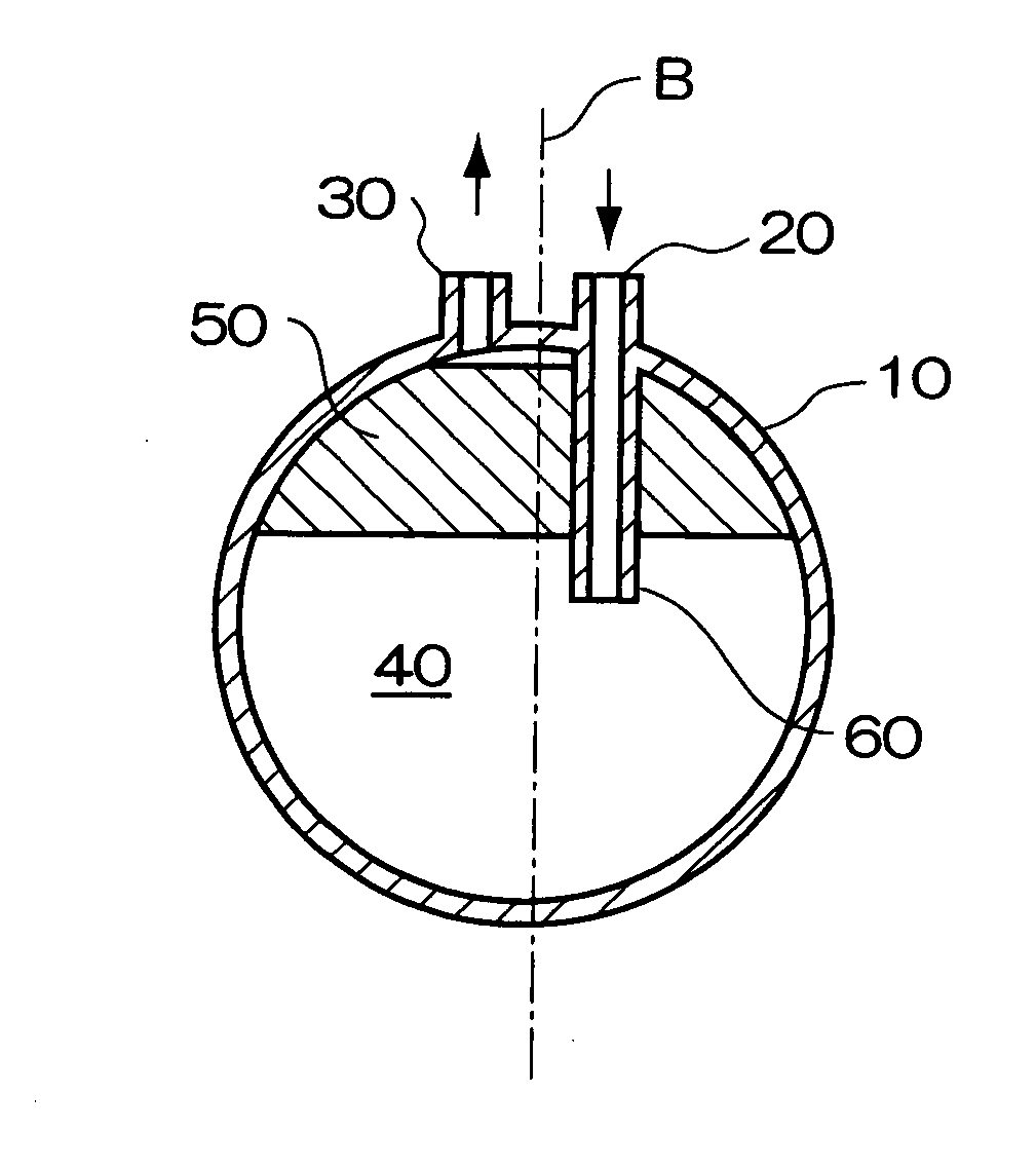
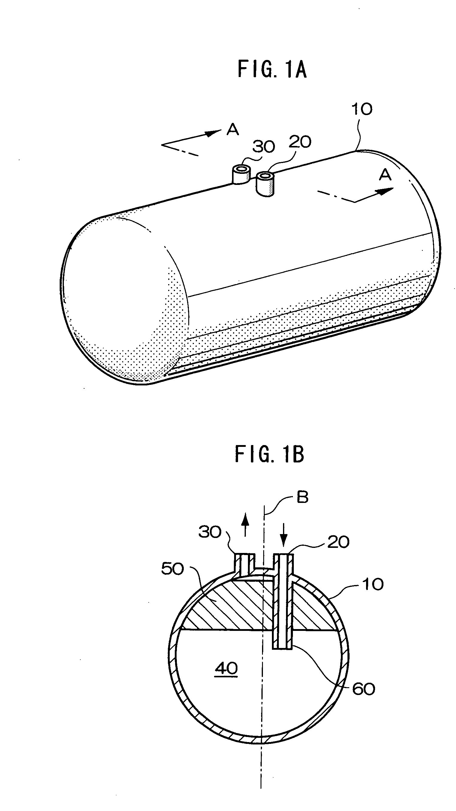
[0038]FIG. 1A is a perspective view of a hydrogen storage device in a first exemplary embodiment of the invention, and FIG. 1B is a sectional view along line A-A of FIG. 1A.
[0039]The hydrogen storage device in the first exemplary embodiment includes a thermally insulated container 10, a liquid hydrogen inflow opening 20 and a hydrogen gas outflow opening 30 disposed in the upper part of the thermally insulated container 10. A hydrogen adsorbing member 50 is disposed at the side opposite the gravitational direction when an inner space 40 of the thermally insulated container 10 is divided so that the volume is 1:1 by an orthogonal plane to a vertical line B (that is, in the upper part of the hydrogen storage device). The liquid hydrogen inflow opening 20 and a portion of the inner space 40 not disposed with the hydrogen adsorbing member 50 communicate with each other by a liquid hydrogen feed pipe 60. The hydrogen gas outflow opening 30 is disposed in the upper part of the thermally i...
second exemplary embodiment
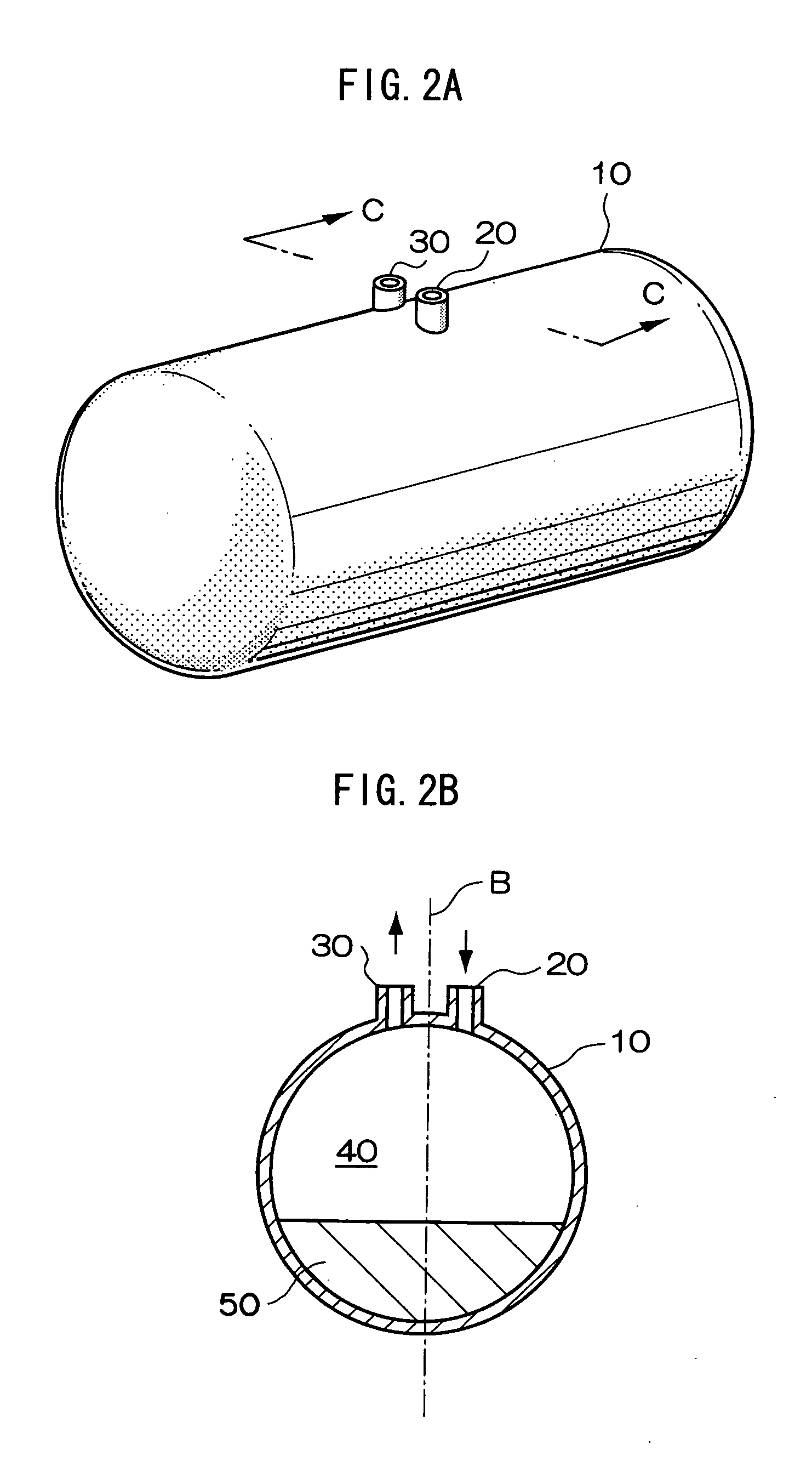
[0049]A hydrogen storage device in a second exemplary embodiment of the invention is described. FIG. 2A is a perspective view of the hydrogen storage device in the second exemplary embodiment of the invention, and FIG. 2B is a sectional view along line C-C of FIG. 2A. The hydrogen storage device in the second exemplary embodiment includes a thermally insulated container 10, a liquid hydrogen inflow opening 20 and a hydrogen gas outflow opening 30 disposed in the upper part of the thermally insulated container 10. A hydrogen adsorbing member 50 is disposed at the gravitational direction side when an inner space 40 of the thermally insulated container 10 is divided so that the volume is 1:1 by an orthogonal plane to a vertical line B (that is, in the lower part of the hydrogen storage device). The thermally insulated container 10 and hydrogen adsorbing member 50 may be same as in the first exemplary embodiment. In this exemplary embodiment, pellets of activated carbon are used, and di...
third exemplary embodiment
[0052]FIG. 3A is a perspective view of a hydrogen storage device in a third exemplary embodiment of the invention, and FIG. 3B is a sectional view along line A-A of FIG. 3A. The hydrogen storage device in the third exemplary embodiment includes a thermally insulated container 110, a liquid hydrogen feed pipe 120 and a hydrogen gas exhaust pipe 130 disposed in the upper part of the thermally insulated container 110. In this exemplary embodiment, the liquid hydrogen feed pipe 120 corresponds to the liquid hydrogen inflow opening, and the hydrogen gas exhaust pipe 130 corresponds to the hydrogen gas outflow opening.
[0053]The thermally insulated container 110 is composed of a tank 112 and a heat insulating material 114 covering the outer side of the tank 112 as shown in FIG. 3B.
[0054]The tank 112 may be SUS or stainless steel tank, but is not limited to this example.
[0055]The heat insulating material 114 may be a multi-layer insulator (MLI). Specific examples of MLI are same as in the f...
PUM
| Property | Measurement | Unit |
|---|---|---|
| pressure | aaaaa | aaaaa |
| volume | aaaaa | aaaaa |
| time | aaaaa | aaaaa |
Abstract
Description
Claims
Application Information