

Filter with integrated loading capacitors
a filter and capacitor technology, applied in the field of high-frequency thin-film multi-layer bandpass filters, can solve the problems of increasing the overall size of the filter substrate, difficult control of the effect, etc., and achieve the effect of improving the skirt performan
- Summary
- Abstract
- Description
- Claims
- Application Information
AI Technical Summary
Benefits of technology
Problems solved by technology
Method used
Image

Examples
Embodiment Construction
[0001]1. Field of the Invention
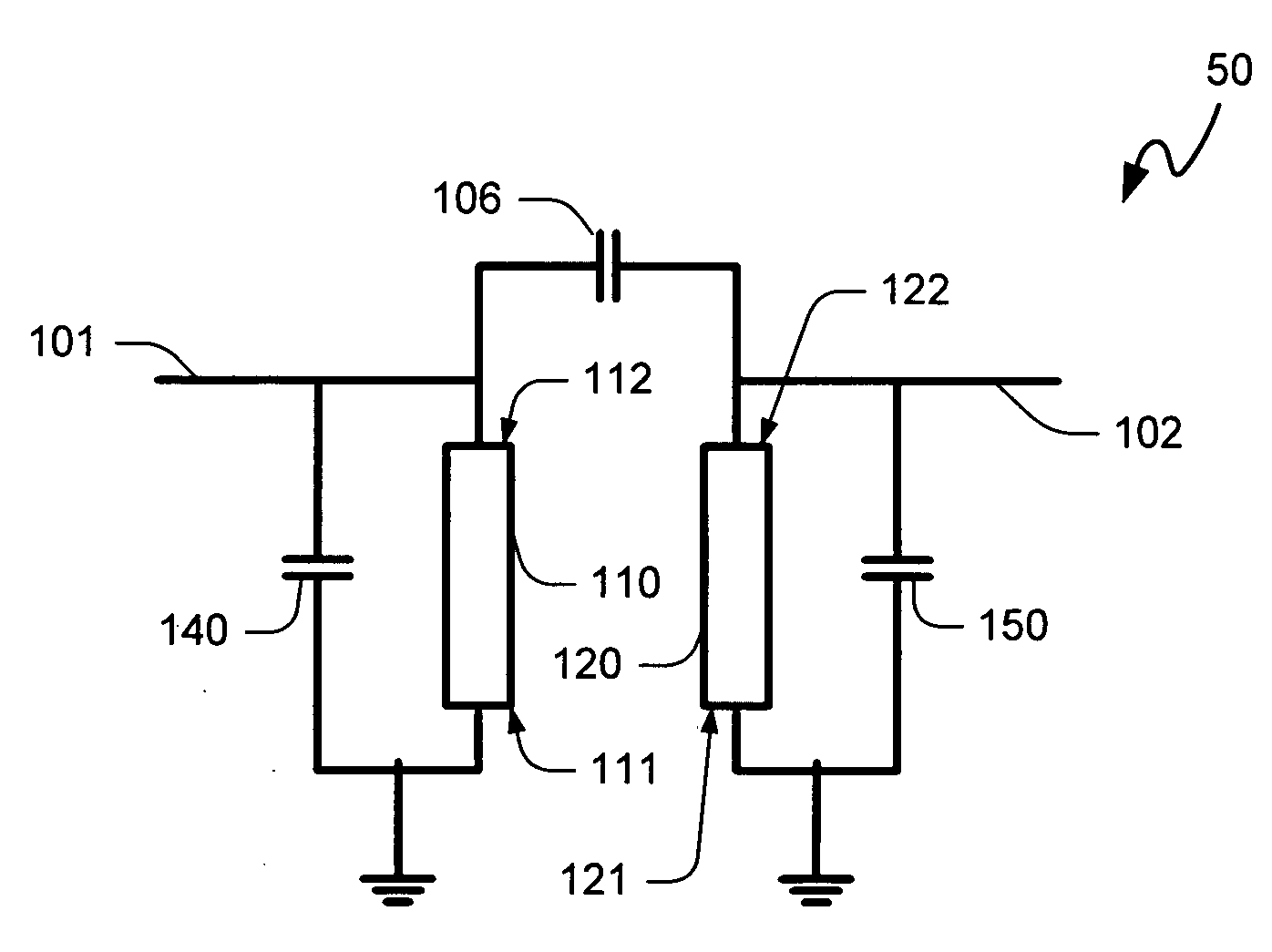
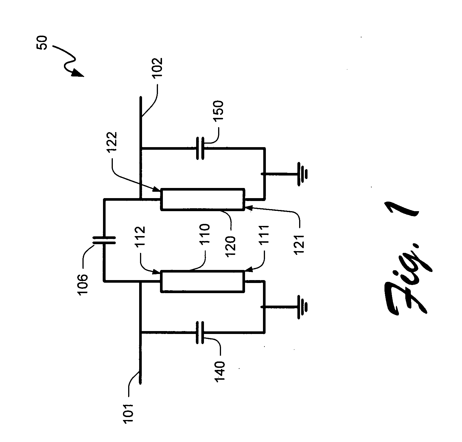
[0002]The present invention relates to electronic bandpass filters, and more specifically to high-frequency thin-film multilayer bandpass filters.
[0003]2. Background of the Invention
[0004]As the development of high performance electronic circuits continues to evolve, market forces have continued to demand ever higher performance and reliability standards with the somewhat paradoxical goals of smaller device sizes and lower costs. Particularly, many communication devices incorporate high-performance complex components such as stripline filter assemblies, and with consumer devices shrinking to ever smaller form factors, size of electronic components is a substantial design concern.
[0005]Traditionally, filters such those implemented in multilayer embodiments such as low-temperature cofired ceramic (LTCC) substrates may incorporate stripline resonators that are usually built with unobstructed dielectric space between the top and bottom ground planes, becau...
PUM
 Abstract
Description
Claims
Application Information