Lens driving device, image stabilizing unit, and image pickup apparatus

a driving device and driving device technology, applied in the direction of cameras, television systems, instruments, etc., can solve the problems of disadvantageous increase of frictional force, and disadvantageous negative impact of mechanisms, and achieve the effect of simplifying the structur

Active Publication Date: 2010-08-26
CANON KK
View PDF4 Cites 20 Cited by
  • Summary
  • Abstract
  • Description
  • Claims
  • Application Information

AI Technical Summary

Benefits of technology

[0014]Accordingly, the present invention provides a lens driving device, an image stabilizing unit, and an image pickup apparatus having a simplified structure in which the location of a support member can be changed relative to a stationary member with an appropriate viscous damping.

Problems solved by technology

However, to obtain a viscous resistance through a mechanical method, the structure is disadvantageously complicated and a frictional force is disadvantageously increased.
In contrast, to obtain a viscous resistance through an electrical method, the mechanism disadvantageously has a negative impact from an assembly-to-assembly variation in an object to be controlled.
In addition, the control system disadvantageously becomes complicated.
However, since this mechanism cannot provide an appropriate viscous resistance, the mechanism is greatly affected by a primary resonance and a sub-resonance, that is, the mechanism is easily affected by disturbance.
However, the structure is not always suitable for image stabilizing units.

Method used


Image

  • Lens driving device, image stabilizing unit, and image pickup apparatus
  • Lens driving device, image stabilizing unit, and image pickup apparatus
  • Lens driving device, image stabilizing unit, and image pickup apparatus

Examples


first exemplary embodiment

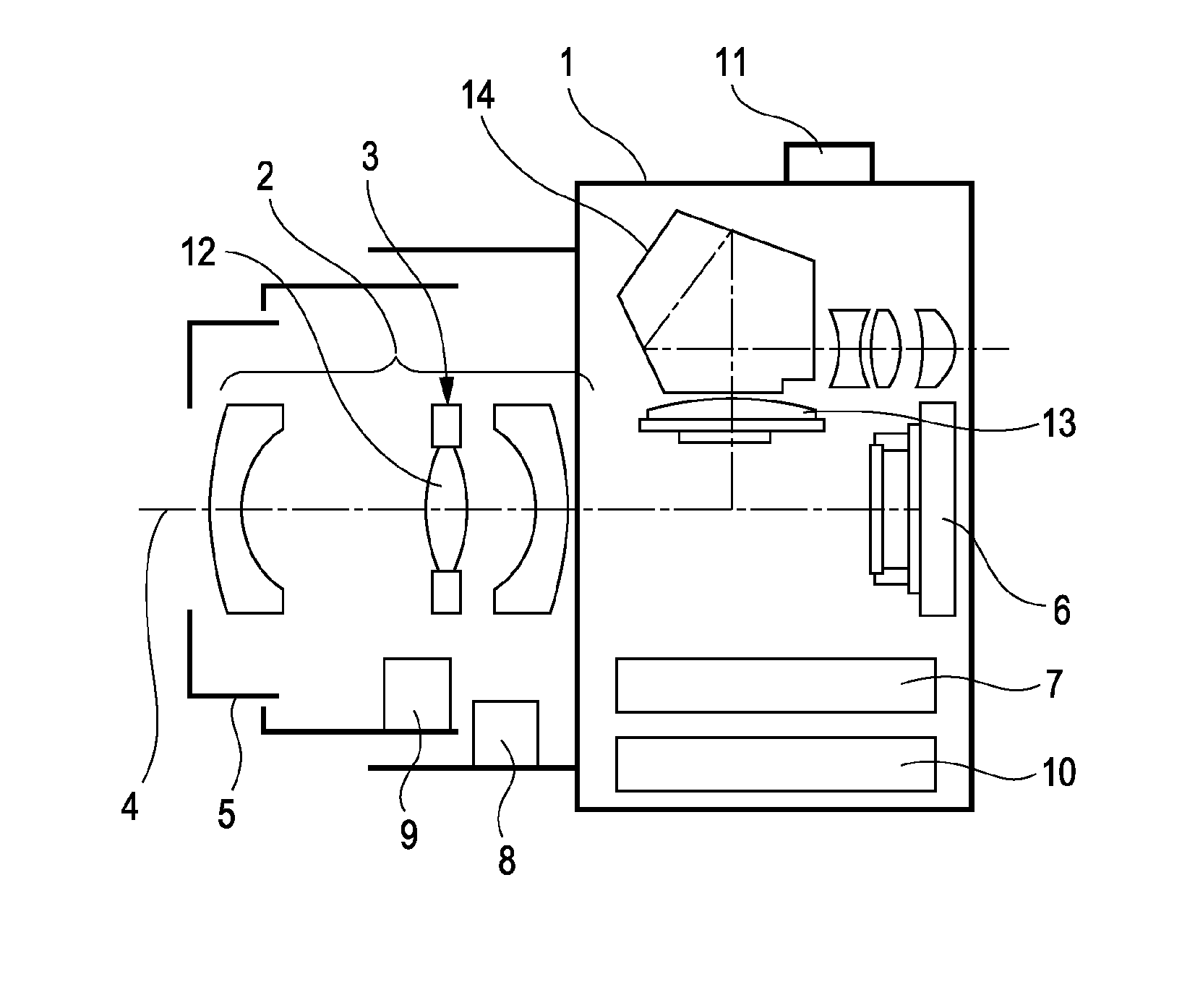
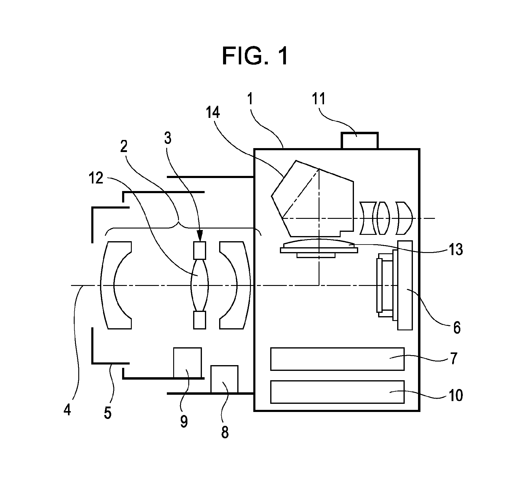
[0056]An image pickup apparatus according to a first exemplary embodiment of the present invention is described below with reference to FIGS. 1 to 16. FIG. 1 illustrates an exemplary structure of the image pickup apparatus. In FIG. 1, an image pickup apparatus 1, an objective taking lens 2, and a lens driving device 3 that drives a compensation lens 12 are shown. In addition, the objective taking lens 2 having a light axis 4, a lens barrel 5, an image pickup element 6, a memory 7, a vibration sensor 8 that detects a vibration, such as a camera shake, and a focus lens driving circuit 9 that drives a focus lens (not shown) incorporated in the objective taking lens 2 are shown. A power supply 10, a release button 11, the compensation lens 12, a quick-return mirror 13, and a finder optical system 14 are also shown. The lens driving device 3 and the vibration sensor 8 form an image stabilizing unit.

[0057]The image pickup apparatus 1 forms an image on the image pickup element 6 or in the ...

second exemplary embodiment

[0106]A second exemplary embodiment of the present invention is described below with reference to FIGS. 18 to 28. Features of components of the image pickup apparatus shown in FIGS. 1 and 2 have been described in the first exemplary embodiment. Therefore, descriptions are not repeated.

[0107]A lens driving device 3 which is a main component of the second exemplary embodiment is described next with reference to FIGS. 18 to 28. FIG. 18 is an exploded perspective view of the lens driving device 3. Similar numbering will be used in describing FIG. 18 as was utilized above in describing the lens driving device 3 according to the first exemplary embodiment. The lens driving device 3 includes a magnet attraction plate 101. The magnet attracting plate 101 is different from the magnet attraction plate 37 according to the first exemplary embodiment in that the magnet attracting plate 101 has an appropriate hole. As can be seen from FIG. 18, a mechanism according to the second exemplary embodim...

third exemplary embodiment

[0129]A third exemplary embodiment of the present invention is described below with reference to FIGS. 29 to 32. Features of components of the image pickup apparatus shown in FIGS. 1 and 2 have been described in the first exemplary embodiment. Therefore, descriptions are not repeated.

[0130]A lens driving device 3 which is a main component of the third exemplary embodiment is described next with reference to FIGS. 29 to 32. FIG. 29 is an exploded perspective view of the lens driving device 3.

[0131]Similar numbering will be used in describing FIG. 29 as was utilized above in describing similar components of the lens driving device 3 according to the first exemplary embodiment. The lens driving device 3 includes slide shafts 201a, 201b, and 201c, a lock ring 202, a lock ring drive motor 203, a rotation prevention bar 204, a fixed yoke 205, and a positioning reference pin 206. The lens driving device 3 further includes screws 207a, 207b, 208, 212a, 212b, and 214, light emitting diodes (...


PUM


Abstract

A lens driving device having a simplified structure in which a holding member is moved relative to a stationary member with appropriate viscous damping is provided. The lens driving device includes the holding member configured to hold a compensation lens for image stabilization, the stationary member configured to support the holding member in a movable manner in a plane that is perpendicular to a light axis, a driving unit configured to change the position of the holding member relative to the stationary member, and a damping material disposed between the holding member and the stationary member. The damping material has a transition region in a frequency range between 0.3 Hz and 100 Hz.

Description

CROSS REFERENCE TO RELATED APPLICATIONS[0001]The present application is a continuation of U.S. patent application Ser. No. 11 / 841,365, filed on Aug. 20, 2007, entitled “LENS DRIVING DEVICE, IMAGE STABILIZING UNIT, AND IMAGE PICKUP APPARATUS”, the content of which is expressly incorporated by reference herein in its entirety. This application also claims priority from Japanese Application No. 2006-233122 filed Aug. 30, 2006, which is hereby incorporated by reference herein in their entirety.BACKGROUND OF THE INVENTION[0002]1. Field of the Invention[0003]The present invention relates to a lens driving device for driving an image stabilizing lens, an image stabilizing unit including the lens driving device, and an image pickup apparatus including the image stabilizing unit.[0004]2. Description of the Related Art[0005]In recent years, with the advent of cameras with increased functionality, many cameras have included an image stabilizing unit that reduces image blur caused by vibration ...

Claims


Application Information

Patent Timeline
Patent Type & Authority Applications(United States)
IPC IPC(8): H04N5/228
CPCG02B27/646
Inventor KIMURA, MASAFUMI
Owner CANON KK
Why Eureka
Try Eureka