Display device, display method and head-up display

a display device and display method technology, applied in the field of display devices, can solve the problems of complex display devices, inability to enhance the perception of depth, and the enormous work required for image processing to produce a plurality of projected images for right-and-left eyes, so as to improve enhance the sense of depth, and improve the effect of realism

Inactive Publication Date: 2010-08-26
KK TOSHIBA
View PDF14 Cites 153 Cited by
  • Summary
  • Abstract
  • Description
  • Claims
  • Application Information

AI Technical Summary

Benefits of technology

[0009]The object the present invention is to provide a display device, a display method and a head-up display which allows the perceivable projected image of the enhanced sense of depth to be achieved easily and a high sense of realism to be displayed without necessity of a complex device configuration and image processing and supports the safer driving of vehicles or the like.Technical Solution

Problems solved by technology

Various methods based on these binocular parallax effects suffer from an enormous work necessary for image processing to produce a plurality of projected images for right-and-left eyes and complexity of display devices.
On the other hand, a projected image may be presented to a one-eye (single eye) in the HMD, however, the perception is limited to a small projected image presented by a display unit placed extremely near to the eye and a high sense of realism can not be presented with the sense of depth.
It is noted that a technique presenting a display image to only one-eye in the HUD is disclosed (Patent Citation 1), however, the technique has no effect enhancing the perception of depth, because it is aimed at preventing double images in visual identification with both eyes.

Method used


Image

  • Display device, display method and head-up display
  • Display device, display method and head-up display
  • Display device, display method and head-up display

Examples


second embodiment

[0122]Next, a second embodiment will be described.

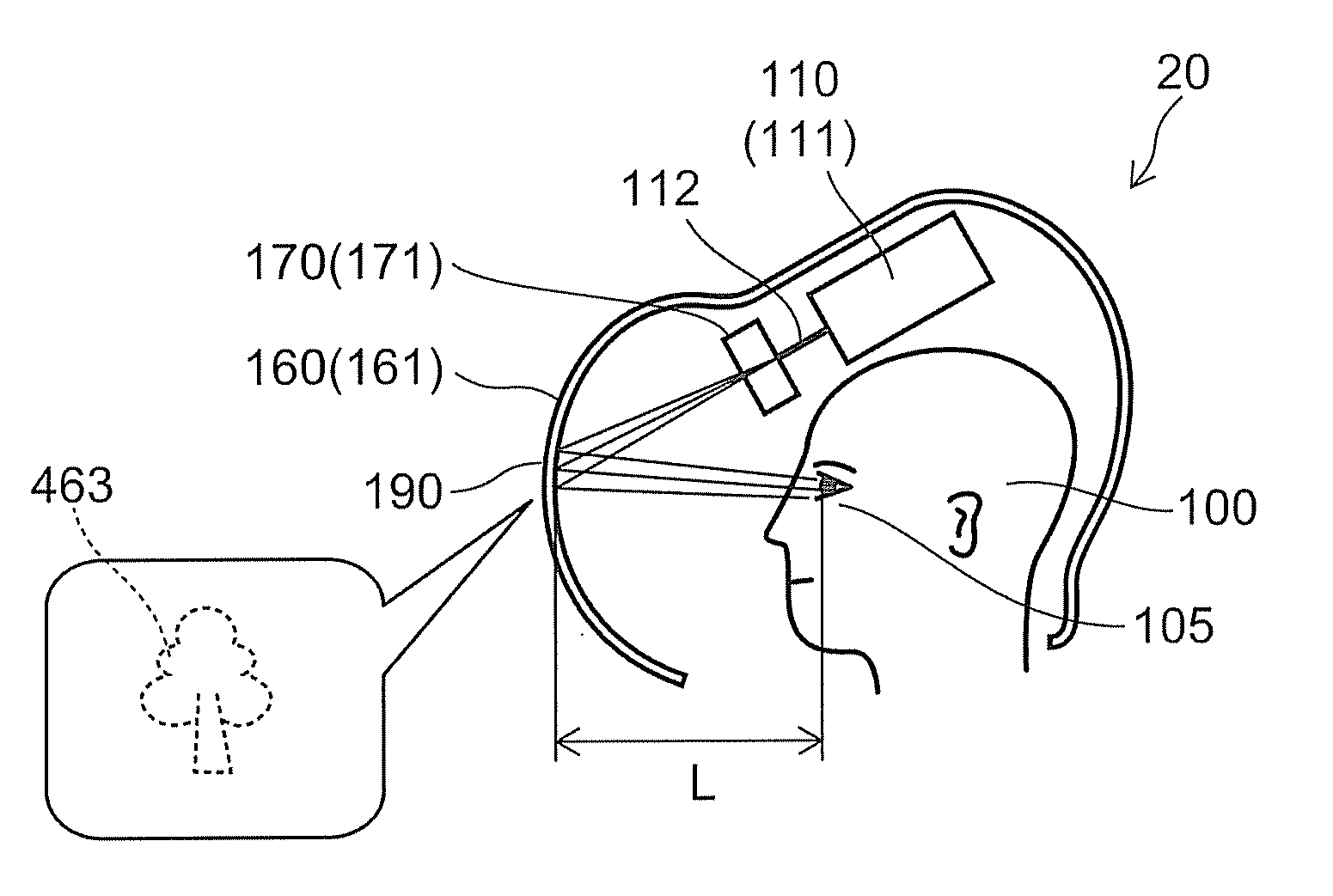
[0123]FIG. 5 is a schematic cross-sectional side view illustrating the configuration of a display device according to a second embodiment of the invention.

[0124]As shown in FIG. 5, a display device 20 of the second embodiment of the invention is a kind of HMD and includes the light flux generation unit 110 generating the light flux 112 containing image information, an image formation unit 160 forming the image on the basis of the light flux 112 and an angle of divergence control unit 170 making the light flux 112 incident to the one-eye of the image viewer by controlling the angle of divergence. It is noted that “control” includes not only active control but also passive control making the flux diverge to have the specified angle of divergence at incidence of the light flux 112 to the angle of divergence control unit 170. The display device 20 includes the field of view control unit illustratively based on the angle of divergence con...

third embodiment

[0156]Next, a third embodiment will be described.

[0157]FIG. 10 is a schematic cross-sectional view illustrating the configuration of a display device according to the third embodiment of the invention.

As shown in FIG. 10, a display device 23 according to the third embodiment of the invention can be based on the projector 111 generating the light flux 112 containing image information as the light flux generation unit 110. The light flux 112 is projected on a lenticular plate 401 through a projection lens 378, the image is formed on the lenticular plate 401 and the real image is formed. This image is reflected by the semi-transparent spherical concave mirror 163b and the virtualized image is projected on the image viewer 100. The virtual image is given, being enlarged by the spherical concave mirror 163b. Moreover, the field of view of the projected image feasible for the image viewer 100 can be varied by the curvature of the concave mirror 163b. In addition, the lenticular plate 401 ...

fourth embodiment

[0162]Next, a fourth embodiment will be described.

[0163]FIG. 11 is a schematic view illustrating the configuration of a display device according to the fourth embodiment of the invention.

As shown in FIG. 11, in a display device 24 of the fourth embodiment, the flat plate mirror 162a and the laminated optical body 168 are used instead of the concave mirror 163b of the display device 23 illustrated in FIG. 10, and additionally an aspheric Fresnel lens 402 serving as a light collecting optical element is placed therebetween. The laminated optical body 168 is composed of the light transmission plate 166b and the semi-transparent highly reflective layer 167.

[0164]In the display device 24 illustrated in FIG. 11, the optical characteristics of the lenticular plate 401 enable the angle of divergence of the light flux 112 to be controlled, and the irradiation region 112a of the light flux 112 can be substantially a circle with a diameter of 6 cm at the position of the image viewer 100. This ...


PUM


Abstract

A display device, generating light flux containing image information and making the light flux incident to one-eye of an image viewer by controlling an angle of divergence of the light flux is provided. The device includes a first lens, a second lens and an angle of divergence control device provided between the first lens and the second lens, the angle of divergence control device being configured to control the angle of divergence of the light flux.

Description

CROSS-REFERENCE TO RELATED APPLICATIONS[0001]This is a continuation application of International Application PCT / JP2008 / 002720, filed on Sep. 29, 2008. This application also claims priority to Japanese Application No. 2007-302584, filed on Nov. 22, 2007. The entire contents of each are incorporated herein by reference.TECHNICAL FIELD[0002]This invention relates to a display device, a display method and a head-up display.BACKGROUND ART[0003]A high quality display device reproducing visual realities for human visual sense has been developed. A sense of depth is extremely important as one of visual realities and technology development for perception of the sense of depth is a critical issue.[0004]Conventionally, the sense of depth for the human visual sense has been considered to be most effected by a binocular parallax. That is, it is said that different images between both eyes are generated by convergence at gazing an object of view by a human and the binocular parallax allows the p...

Claims


Application Information

Patent Timeline
Patent Type & Authority Applications(United States)
IPC IPC(8): G02B26/08G02B27/10G02B5/04G02B5/32
CPCG02B3/0087G02B6/00G02B27/0101G02B27/0103G02B2027/0187G02B2027/0134G02B2027/0138G02B2027/0174G02B27/0172
Inventor SASAKI, TAKASHIHOTTA, AIRAOKUMURA, HARUHIKOOKADA, NAOTADAHORIUCHI, KAZUO
Owner KK TOSHIBA
Why Eureka
Try Eureka