
Thin film electrochemical energy storage device with three-dimensional anodic structure

a technology of energy storage device and thin film, which is applied in the field of thin film electrochemical energy storage device with three-dimensional anodic structure, can solve the problems of limiting the minimum size of the electrode constructed from such materials, and reducing the service life of the devi

Inactive Publication Date: 2010-08-26
APPLIED MATERIALS INC
View PDF10 Cites 126 Cited by
  • Summary
  • Abstract
  • Description
  • Claims
  • Application Information

AI Technical Summary

Problems solved by technology

In addition, the size, weight, and / or expense of such energy storage devices can be significant limitations.
Namely, such materials limit the minimum size of the electrodes constructed from such materials, produce unfavorable internal resistance in an energy storage device, and require complex and eclectic manufacturing methods.

Method used


Image

  • Thin film electrochemical energy storage device with three-dimensional anodic structure
  • Thin film electrochemical energy storage device with three-dimensional anodic structure
  • Thin film electrochemical energy storage device with three-dimensional anodic structure

Examples


Embodiment Construction

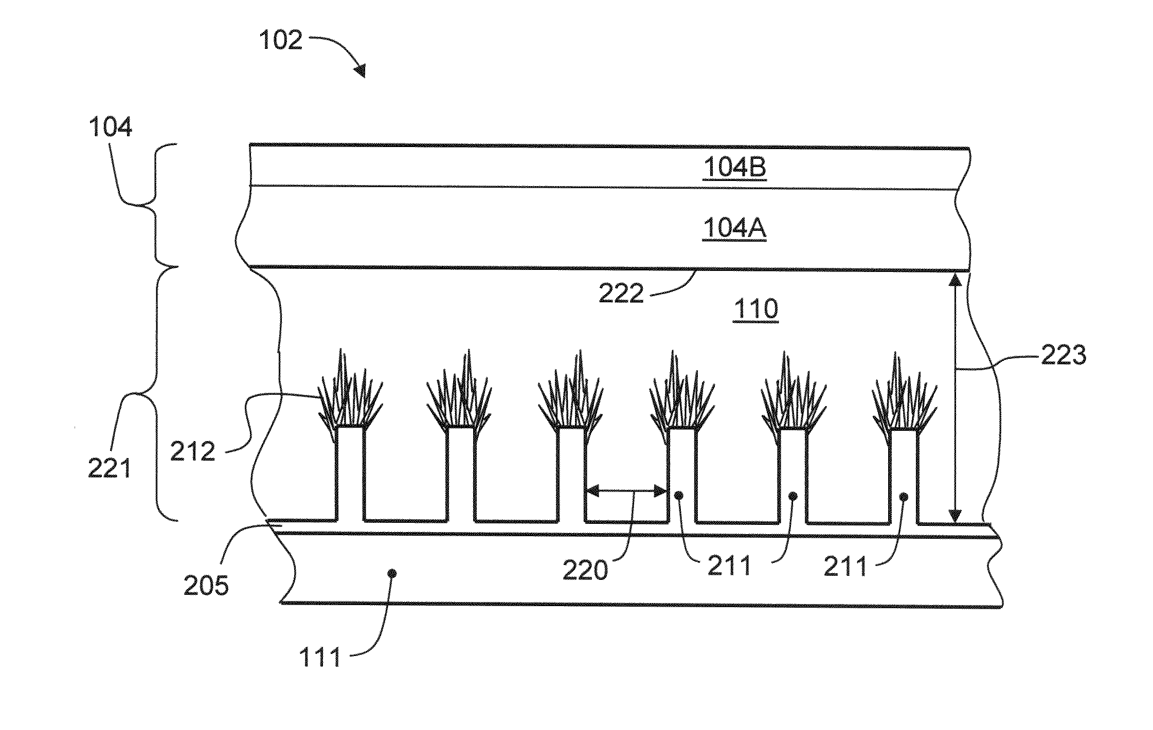
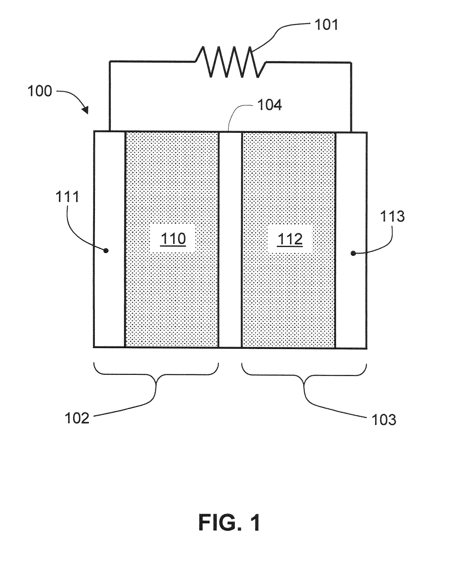
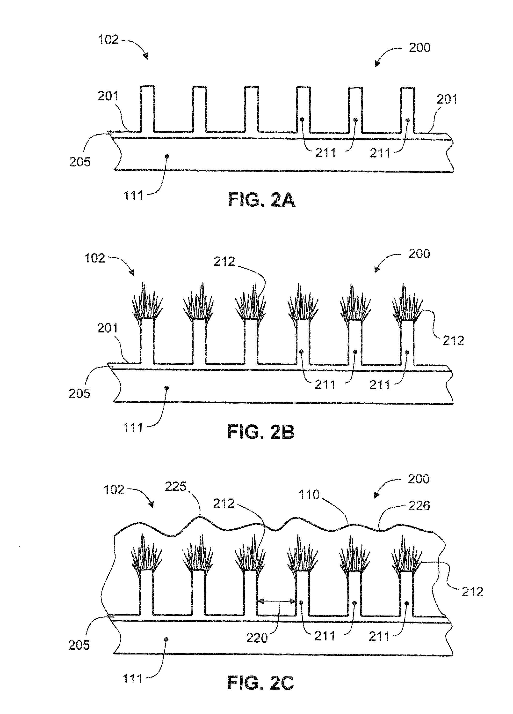
[0034]Embodiments of the invention contemplate forming an electrochemical device, such as a battery or supercapacitor, using thin-film deposition processes and other methods of forming the same. The embodiments described herein include the deposition of a mesoporous carbon material onto a surface of a conductive substrate that has high surface area to form conductive micro-structures thereon. A mesoporous material, as defined herein, is a material containing pores with diameters between about 2 nanometers (nm) and about 50 nm. A porous, dielectric separator layer is then deposited on the layer of mesoporous carbon material to form a half cell of an energy storage device, such as an anodic structure for a Li-ion battery, or half of a super capacitor. The mesoporous carbon material is made up of CVD-deposited carbon fullerene “onions” and / or carbon nano-tubes (CNTs), both of which are capable of retaining lithium ions in concentrations useful for storing significant quantities of elec...


PUM

PropertyMeasurementUnit
Fractionaaaaaaaaaa
Fractionaaaaaaaaaa
Fractionaaaaaaaaaa

Abstract

A method for forming a battery from via thin-film deposition processes is disclosed. A mesoporous carbon material is deposited onto a surface of a conductive substrate that has high surface area, conductive micro-structures formed thereon. A porous, dielectric separator layer is then deposited on the layer of mesoporous carbon material to form a half cell of an energy storage device. The mesoporous carbon material is made up of CVD-deposited carbon fullerene “onions” and carbon nano-tubes, and has a high porosity capable of retaining lithium ions in concentrations useful for storing significant quantities of electrical energy. Embodiments of the invention further provide for the formation of an electrode having a high surface area conductive region that is useful in a battery structure. In one configuration the electrode has a high surface area conductive region comprising a porous dendritic structure that can be formed by electroplating, physical vapor deposition, chemical vapor deposition, thermal spraying, and / or electroless plating techniques.

Description

CROSS-REFERENCE TO RELATED APPLICATIONS[0001]This application claims the benefit of U.S. Provisional Patent Application Ser. No. 61 / 156,862 (APPM / 013529L02), filed Mar. 2, 2009 and U.S. Provisional Patent Application Ser. No. 61 / 155,454 (APPM / 013529L), filed Feb. 25, 2009, which are both herein incorporated by reference.BACKGROUND OF THE INVENTION[0002]1. Field of the Invention[0003]Embodiments of the present invention relate generally to lithium-ion batteries, and more specifically, to a method of fabricating such batteries using thin-film deposition processes that form three-dimensional structures.[0004]2. Description of the Related Art[0005]Fast-charging, high-capacity energy storage devices, such as supercapacitors and lithium—(Li) ion batteries, are used in a growing number of applications, including portable electronics, medical, transportation, grid-connected large energy storage, renewable energy storage, and uninterruptible power supply (UPS). In modern rechargeable energy ...

Claims


Application Information

Patent Timeline
IPC IPC(8): H01M2/16C25D5/00H01M50/417H01M50/451H01M50/457
CPCC25D1/00C25D1/006H01M2/1686H01M4/0428H01M4/133H01M4/1393H01M4/364H01M4/587H01M4/667H01M4/70H01M6/40H01M10/0525H01M10/0565H01M10/0566H01M10/058H01M10/0585Y02E60/122H01M2/1653Y02E60/10Y02P70/50H01M50/417H01M50/451H01M50/457H01M4/02H01M4/04H01M4/13H01M4/366H01M2004/027
Inventor LOPATIN, SERGEY D.BREVNOV, DMITRI A.BACHRACH, ROBERT Z.
Owner APPLIED MATERIALS INC
Learn More