
Apparatus for providing coolant fluid

Active Publication Date: 2010-08-26
CANNON DESIGN +1
View PDF18 Cites 8 Cited by
  • Summary
  • Abstract
  • Description
  • Claims
  • Application Information

AI Technical Summary

Benefits of technology

[0009]It is a general object of the present invention to provide cooling fluid apparatus having a minimal volume which can provide cooling fluid in an appropriate pressure range, flow rate and temperature range.
[0010]It is another general object of the present invention to isolate a building chilled fluid loop from the device chilled fluid loop thereby preventing flooding due to connection failures.
[0011]It is yet another object of the present invention to provide a cooling fluid apparatus which is plug and play, i.e., the apparatus can be moved from one location to another with a minimal setup and configuration and to provide a cooling fluid apparatus that can be mounted within the vented enclosure of a fume hood.
[0012]It is still yet another object of the present invention to provide cooling fluid in an environmentally friendly way and at a minimum of cost.

Problems solved by technology

Laboratory environments present a multitude of challenges for instrument design and the conducting of experiments and procedures.
This arrangement suffers from several drawbacks which include a large, wasteful use of a natural resource, i.e., water, potential flooding in a lab, poor temperature control and the elimination of sinks for other uses.
In like fashion, these systems, in addition to the aforementioned drawbacks, also suffer from several other drawbacks which can include water pressures at elevated or dangerous levels and temperatures which are too cool.
Furthermore, as in the instance of using a chilled water supply, high fluid pressures may be impractical for use with all laboratory equipment as some equipment may rupture when subjected to elevated pressures.
This flexibility is sometimes desirable when demand for cooling fluid is low; however, if demand for cooling fluid is high, multiple water baths are necessary.
Even though these baths provide this flexibility, they suffer from drawbacks such as being expensive, i.e., approximately three to eight thousand dollars per unit, they are large, noisy, provide too great of a flow rate and / or too much pressure.
Additionally, such systems are not appropriate for placement within a fume hood as their size prohibits it and the corrosive environment within a fume hood will degrade device enclosures and internal components.
Moreover, these devices are fixed in size, shape and usage, and therefore do not offer scaling up to larger sizes or ease of servicing.
Heretofore, tradeoffs between costs, resource consumption and flexibility were required.

Method used


Image

  • Apparatus for providing coolant fluid
  • Apparatus for providing coolant fluid
  • Apparatus for providing coolant fluid

Examples


Embodiment Construction

[0022]At the outset, it should be appreciated that like drawing numbers on different drawing views identify identical, or functionally similar, structural elements of the invention. While the present invention is described with respect to what is presently considered to be the preferred aspects, it is to be understood that the invention as claimed is not limited to the disclosed aspects.

[0023]Furthermore, it is understood that this invention is not limited to the particular methodology, materials and modifications described and as such may, of course, vary. It is also understood that the terminology used herein is for the purpose of describing particular aspects only, and is not intended to limit the scope of the present invention, which is limited only by the appended claims.

[0024]Unless defined otherwise, all technical and scientific terms used herein have the same meaning as commonly understood to one of ordinary skill in the art to which this invention belongs. It should be appr...


PUM


Abstract

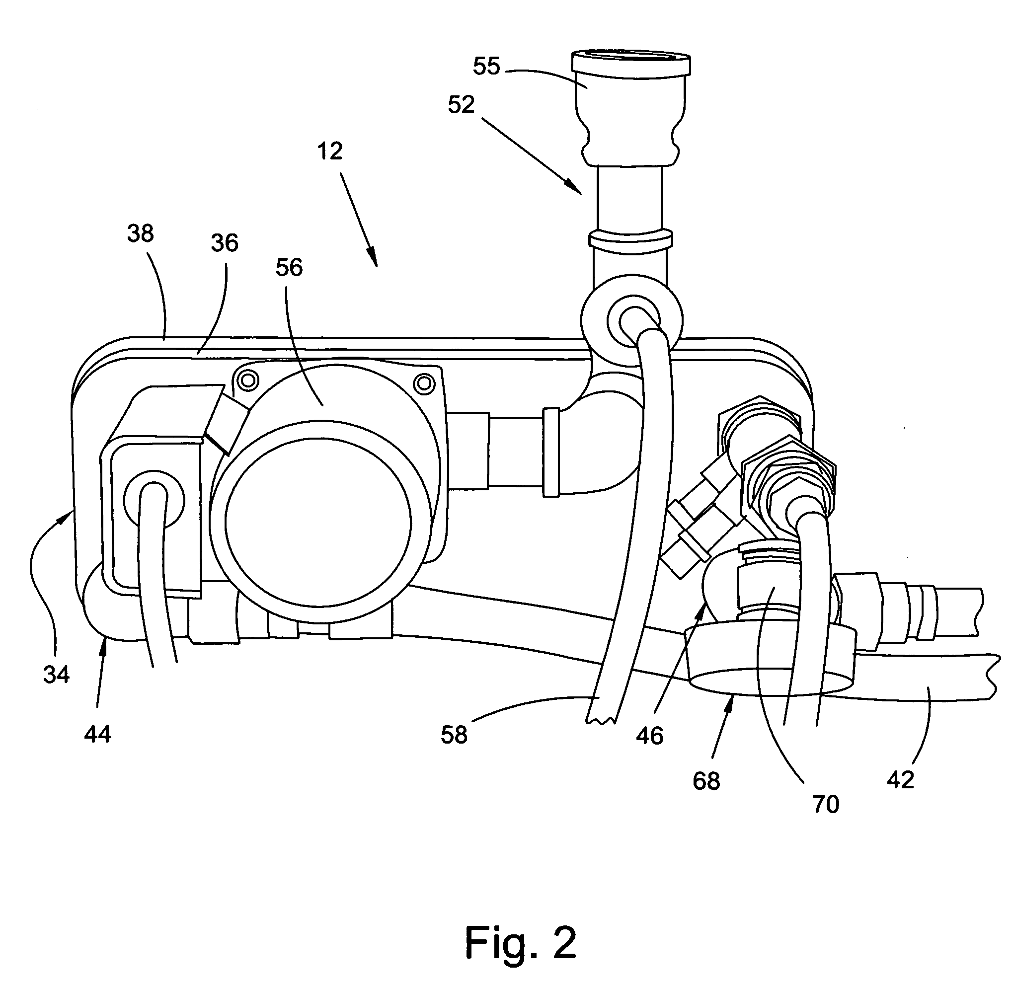
An apparatus for providing coolant fluid to a device, the apparatus includes a heat exchanger having a hot side and a cold side. The cold side is in fluid communication with a chilled fluid supply and adapted to receive a first fluid from the chilled fluid supply in a first inlet and return the first fluid from the cold side to the chilled fluid supply. The cold side and the chilled fluid supply form a first fluid circuit. The apparatus further includes a second fluid circuit in fluid communication with the hot side, means for introducing a second fluid within the second fluid circuit and integral thereto, a pump integral to the second fluid circuit and adapted to transmit a second fluid within the second fluid circuit and means for controlling a rate of flow of the second fluid within the second fluid circuit. The device is within the second fluid circuit and the means for controlling the rate of flow operates in the absence of internal recirculation.

Description

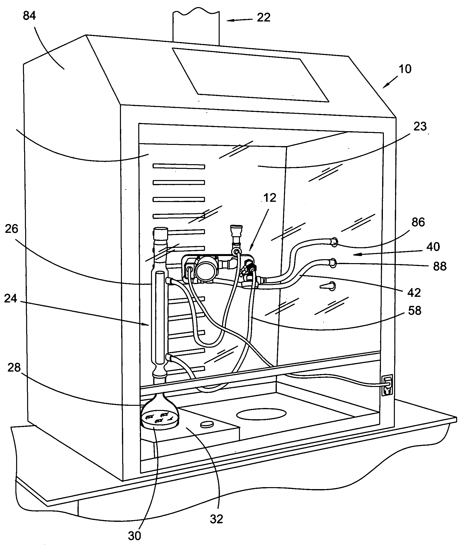
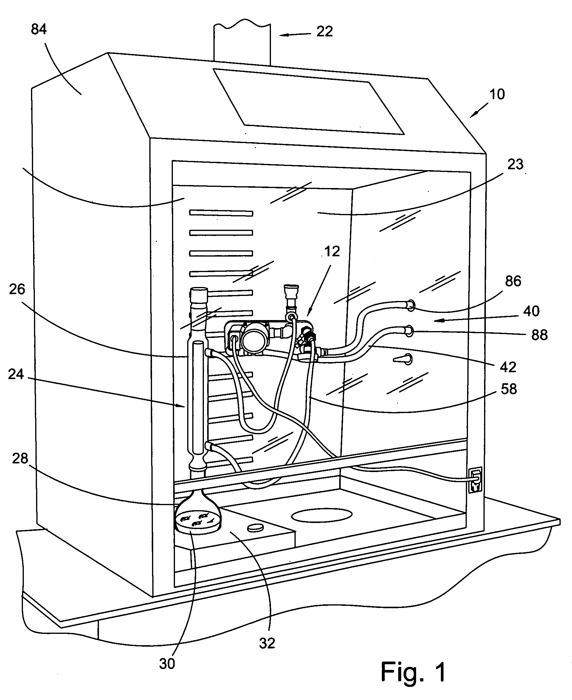
FIELD OF THE INVENTION[0001]The invention broadly relates to heat exchangers, more specifically to a heat exchanger arranged to provide coolant fluid, and even more particularly to a heat exchanger adapted to be mounted within a laboratory fume hood and arranged to provide coolant fluid.BACKGROUND OF THE INVENTION[0002]Laboratory environments present a multitude of challenges for instrument design and the conducting of experiments and procedures. In particular, chemistry labs of various types often require specific and dedicated equipment for a variety of experiment setups. For example, some apparatus require the circulation of cooling fluid therein. Such equipment may include, but are not limited to, rotary evaporators, lasers, reflux condenser columns, distillation columns, condenser columns, etc. These types of equipment are commonly used in universities, research and development and government agencies worldwide.[0003]Various techniques are known in the art for providing the nec...

Claims


Application Information

Patent Timeline
IPC IPC(8): B08B15/02F28F3/08F28F27/02F24H9/00
CPCB01L2300/185B01L1/50
Inventor WILLIAMS, GERALD G.HAGER, ANDREW D.
Owner CANNON DESIGN
Learn More