
Water electrolysis system

a water electrolysis and water adsorption technology, applied in the field of water electrolysis system, can solve the problems of large amount of adsorbent becoming considerably large in size, inability to adsorb water well, and inability to supply economical, etc., to achieve the effect of efficiently supplying desired dry hydrogen, simple structure and reliably preventing water from being contained in hydrogen

Inactive Publication Date: 2010-09-02
HONDA MOTOR CO LTD
View PDF5 Cites 12 Cited by
  • Summary
  • Abstract
  • Description
  • Claims
  • Application Information

AI Technical Summary

Benefits of technology

[0014]It is an object of the present invention to provide a water electrolysis system of simple structure which is capable of reliably preventing water contained in hydrogen from passing through a water adsorption apparatus and hence of efficiently supplying desired dry hydrogen.
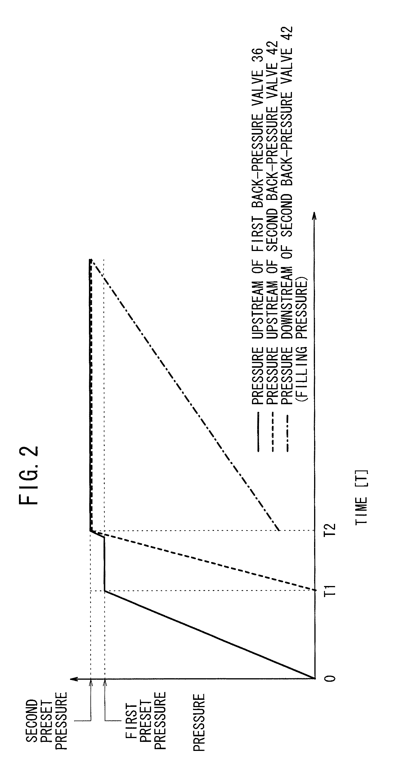
[0017]According to the present invention, since the second pressure regulating valve is connected downstream of the water adsorption apparatus, the pressure acting in the water adsorbing apparatus can be kept at a preset pressure. Therefore, hydrogen containing water does not quickly flow through the water adsorbing apparatus, which is thus able to reliably adsorb the water contained in the hydrogen. Further, as the pressure acting in the water adsorbing apparatus is kept at a preset pressure, the adsorbed water in the water adsorbing apparatus is prevented from being released therefrom and flowing downstream of the water adsorbing apparatus.
[0018]Further, the first pressure regulating valve is connected between the hydrogen outlet and the water adsorbing apparatus. As a result, the water adsorbing apparatus can be isolated from the region upstream thereof. Thus, the water adsorbing apparatus, for example, can be cleaned easily and efficiently. Therefore, the water electrolysis system is of a relatively simple structure for reliably preventing water contained in the hydrogen from passing through the water adsorbing apparatus, and also for efficiently supplying desired dry hydrogen.

Problems solved by technology

When the high-pressure hydrogen is abruptly introduced into the water adsorption tube 5, the water adsorption tube 5 may not be able to adsorb water well from the high-pressure hydrogen because the high-pressure hydrogen flows at an excessively high speed.
However, the water adsorption tube 5 with a large amount of adsorbent will become considerably large in size and is not economical.

Method used


Image

  • Water electrolysis system
  • Water electrolysis system
  • Water electrolysis system

Examples


Embodiment Construction

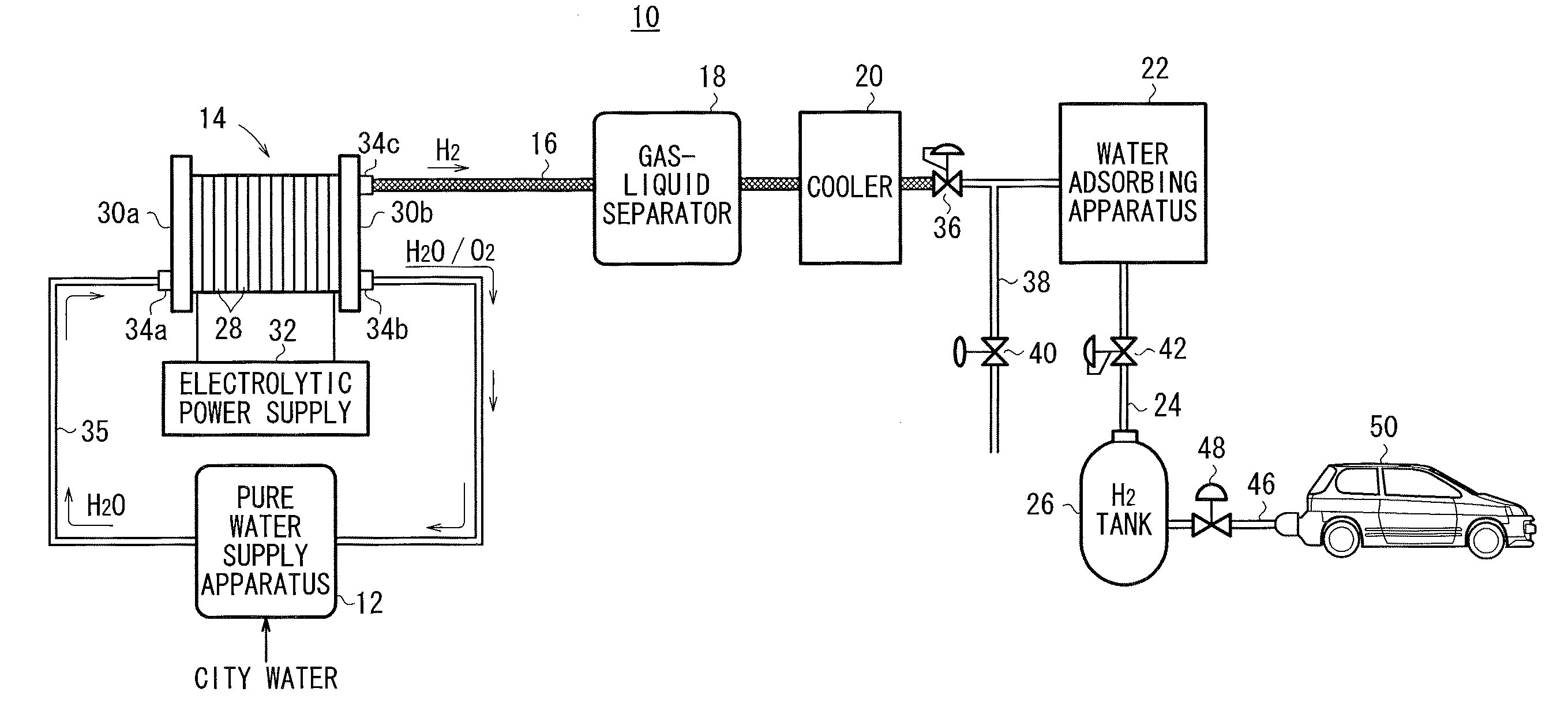
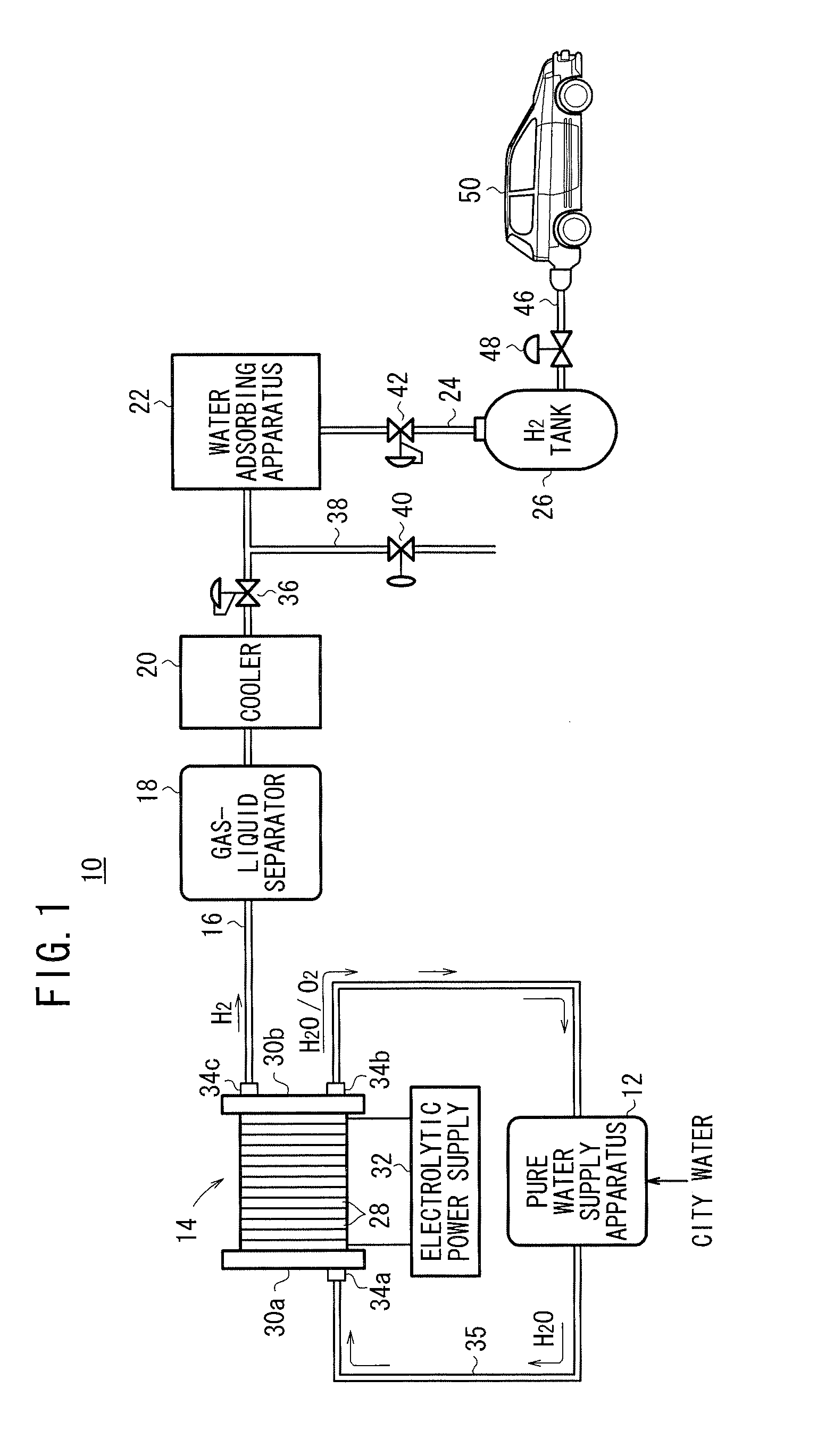
[0027]As shown in FIG. 1, a water electrolysis system 10 according to an embodiment of the present invention comprises a water electrolysis apparatus 14 for being supplied with pure water that has been generated from city water from a pure water supply apparatus 12 and electrolyzing the pure water to produce high-pressure hydrogen (whose pressure is higher than a normal pressure), a gas-liquid separator 18 for removing water contained in the high-pressure hydrogen which is delivered from the water electrolysis apparatus 14 into a hydrogen outlet passage 16, a cooler 20 for cooling the hydrogen discharged from the gas-liquid separator 18, a water adsorbing apparatus 22 for adsorbing away water contained in the cooled hydrogen discharged from the cooler 20, and a hydrogen tank 26 for storing the hydrogen (dry hydrogen) delivered from the water adsorbing apparatus 22 into a dry hydrogen supply passage 24. The hydrogen tank 26 is optional, and may be added when necessary or may be dispe...


PUM

PropertyMeasurementUnit
Pressureaaaaaaaaaa

Abstract

A water electrolysis system includes a water electrolysis apparatus for electrolyzing pure water supplied from a pure water supply apparatus for manufacturing high-pressure hydrogen. The water electrolysis apparatus has a pipe serving as a hydrogen outlet to which a gas-liquid separator, a cooler, and a water adsorption apparatus are successively connected in this order along the direction in which hydrogen is discharged from the water electrolysis apparatus. A first back-pressure valve is connected between the cooler and the water adsorption apparatus, and a second back-pressure valve is connected downstream of the water adsorption apparatus.

Description

CROSS-REFERENCE TO RELATED APPLICATION[0001]This application is based upon and claims the benefit of priority from Patent Application No. 2009-045708 filed on Feb. 27, 2009, in the Japan Patent Office, of which the contents are incorporated herein by reference.BACKGROUND OF THE INVENTION[0002]1. Field of the Invention[0003]The present invention relates to a water electrolysis system having a water electrolysis apparatus for electrolyzing water with an electric current supplied from a DC power supply to generate hydrogen and oxygen, and a water adsorbing apparatus for adsorbing water in the hydrogen generated by the water electrolysis apparatus, the water adsorbing apparatus being connected downstream of a hydrogen discharge port of the water electrolysis apparatus which discharges the hydrogen.[0004]2. Description of the Related Art[0005]Solid polymer electrolyte fuel cells generate DC electric energy when anodes thereof are supplied with a fuel gas, i.e., a gas mainly composed of h...

Claims


Application Information

Patent Timeline
IPC IPC(8): C25B9/00
CPCC25B1/04C25B15/08Y02E60/50Y02E60/366H01M8/0656Y02E60/36
Inventor TAKEUCHI, JUNOKABE, MASANORINAKAZAWA, KOJITARUYA, KENJI
Owner HONDA MOTOR CO LTD
Learn More