
Frame buffer compression for video processing devices

Active Publication Date: 2010-09-02
ZORAN CORPORATION
View PDF9 Cites 38 Cited by
  • Summary
  • Abstract
  • Description
  • Claims
  • Application Information

AI Technical Summary

Benefits of technology

[0022]The image coefficients are grouped into relatively small blocks of coefficients (e.g. 4×4 or 8×8 coefficients) that are each represented with the same number of bits. A coefficient block corresponds to a small region of the frame (e.g. 4×4 or 8×8 pixels). This allows performing a direct memory access to a compressed frame buffer with minimal overhead.
[0024]The compression method affords selective access to the frame data in a scalable way. Low-definition information can be accessed separately at low cost, and when high-definition information becomes necessary, additional and larger information can be loaded from the frame buffer off a separate layer to refine the coarse scale pixel information. This is an advantage provided by using a local multiscale transform such as a wavelet transform in the compression method.
[0049]When the compressed video signal is available according to luma and chroma channels (initially or after a change of color coordinate system), the coding data generated from the signal component of the luma channel can be allocated more bits than the coding data generated from the signal component of each chroma channel. This makes it possible to optimize the compression ratio while keeping a good quality of the signal.
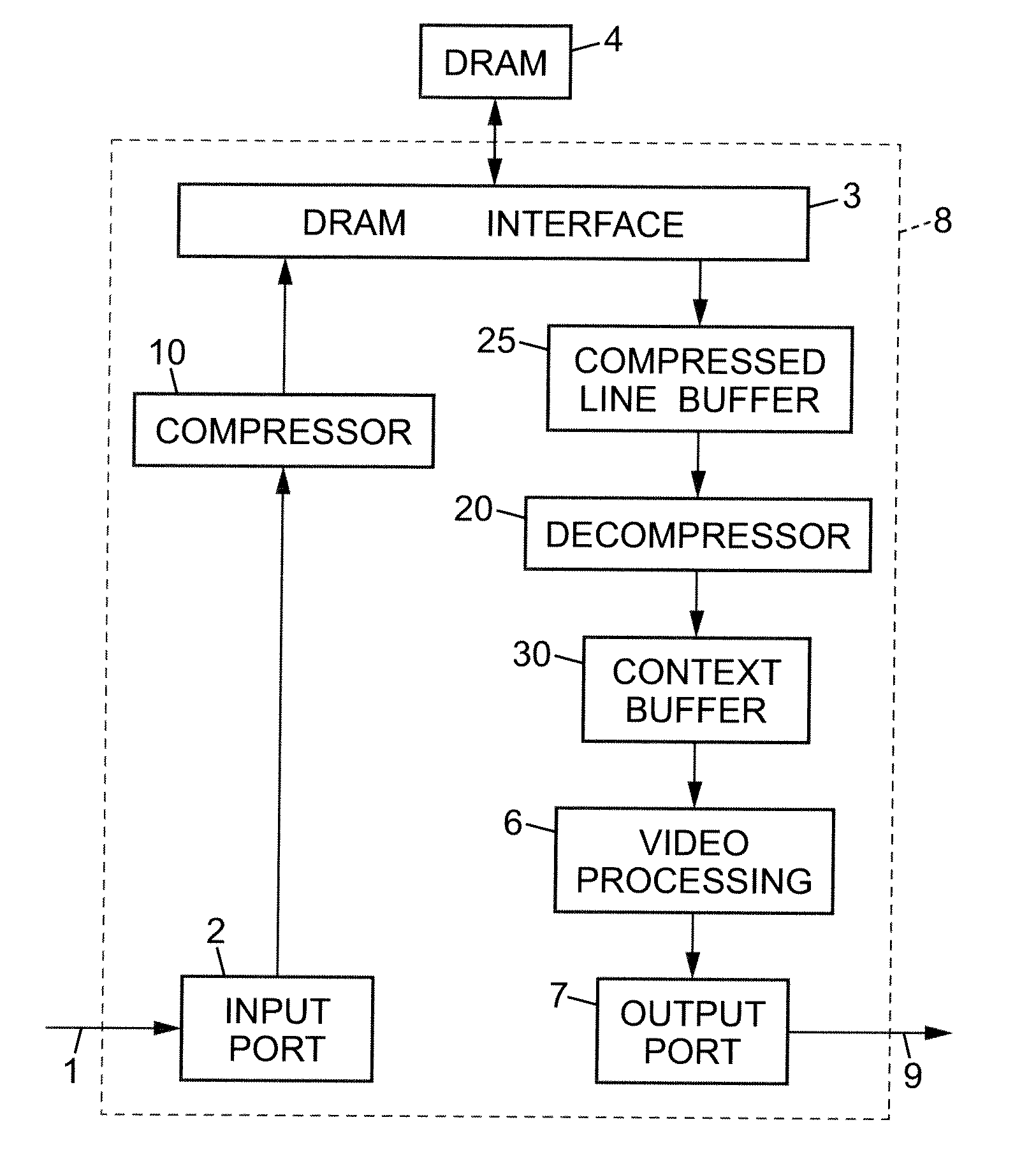
[0061]Such an embodiment makes it possible for the compression to reduce not only the size of the external frame buffer but also that of the internal line buffer of the device. Only a small context portion needs to be stored explicitly in the decompressed form.

Problems solved by technology

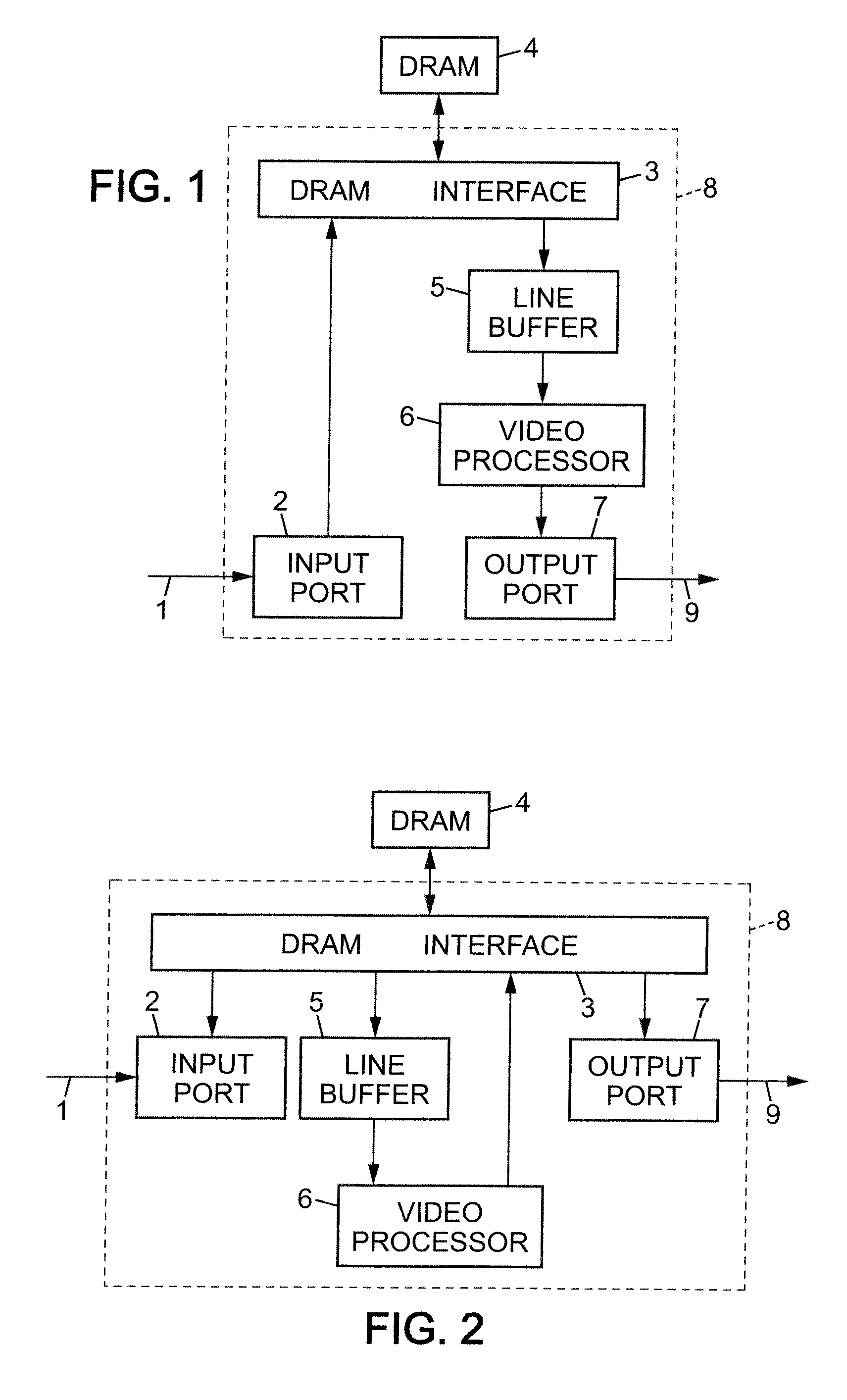
In a video processing device embodied as an application-specific integrated circuit (ASIC) or a field-programmable gate array (FPGA), input frames are stored in a frame buffer usually located in external memory, because they do not fit in the device itself.
High transfer rates between the device 8 and the DRAM 4 are not desirable because they may require using a higher number of DRAM chips in parallel.
Hosting such a large line buffer in an ASIC is expensive, because it increases the die size of the ASIC, and has a negative impact on the manufacturing yield.
They are not adapted though, because in most cases random access to an image region is not possible without decompressing the entire image.

Method used


Image

  • Frame buffer compression for video processing devices
  • Frame buffer compression for video processing devices
  • Frame buffer compression for video processing devices

Examples


Embodiment Construction

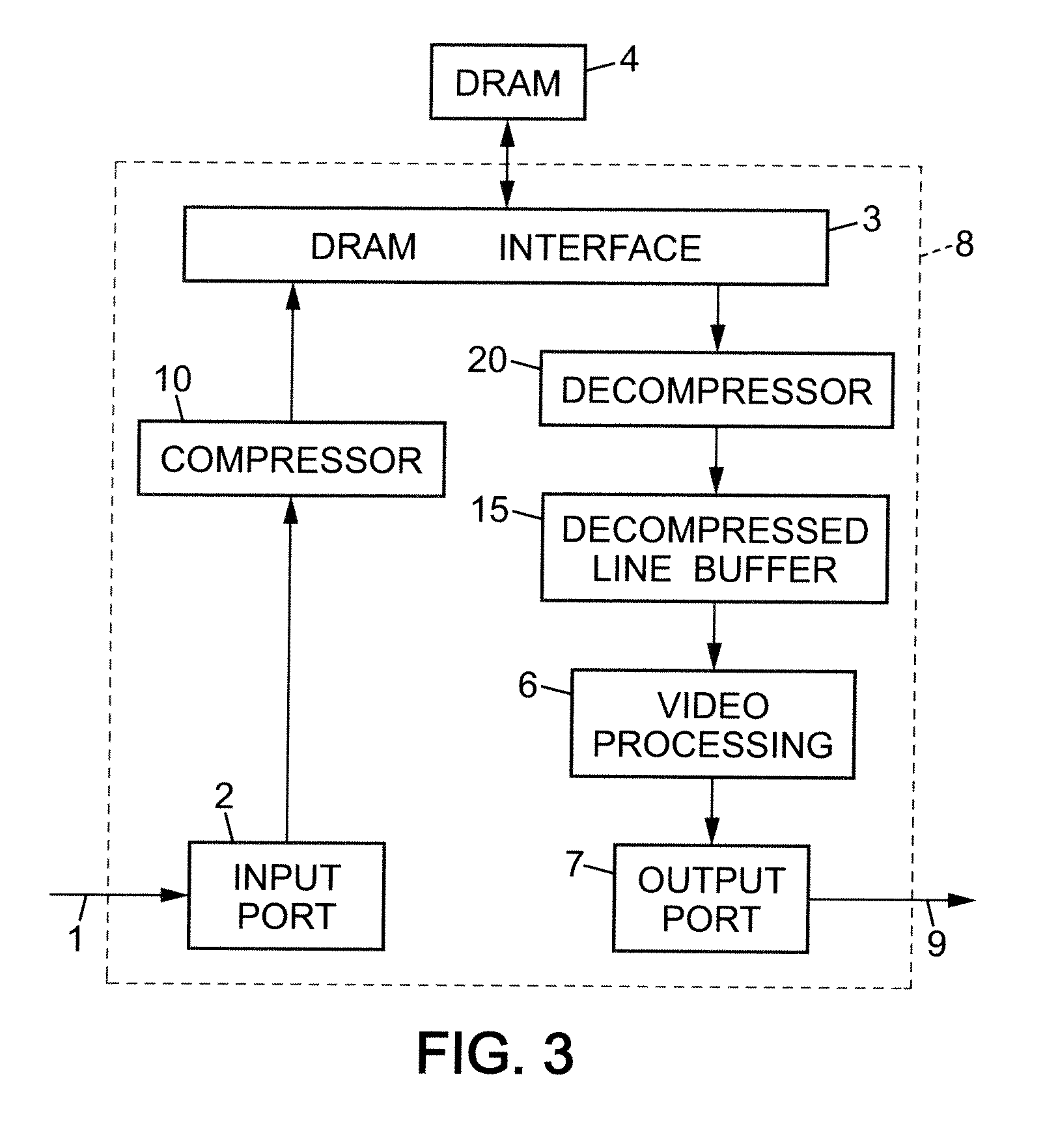
[0071]Compression can be used for reducing the need for internal memory inside a video processing device 8 as discussed in the introduction. This is illustrated in FIG. 4. The line information is transferred in a compressed form from the DRAM 4 to be stored into a compressed line buffer 25 whose size, compared to the decompressed line buffer 15 of FIG. 3, is reduced by the compression factor. The decoder 20 decompresses on-the-fly pixels from the line buffer 25 to store decompressed pixels in a small-sized context buffer 30.

[0072]On-the-fly decompression of the context portion is performed as the video processor 6 is proceeding along a line of the current output frame. FIG. 5 illustrates the operation of decoder 20 in the video processing device 8 of FIG. 4. The compressed line buffer 25 contains coding data corresponding to a horizontal stripe 51 of pixels. As an example, the uncompressed pixels are each made of 30 bits in RGB representation and the compression factor is 2:1, so th...


PUM


Abstract

For compressing a video signal, a local multiscale transform is applied to a frame of the video signal to obtain coefficient blocks. The coefficients of each block are distributed into a plurality of coefficient groups, and for at least one of the groups, a common exponent is determined for encoding the coefficients of the group, and respective mantissas are determined for quantizing the coefficients of the group in combination with the common exponent. Coding data including each exponent determined for a coefficient group and the mantissas quantizing the coefficients of the group in combination with this exponent are stored in an external frame buffer.

Description

BACKGROUND OF THE INVENTION[0001]The present invention relates to video processing and in particular to real-time video processing in dedicated hardware devices.[0002]In the design of such dedicated hardware video processing devices, it is generally desired to reduce the need for external memory components, and for internal memory.[0003]In a video processing device embodied as an application-specific integrated circuit (ASIC) or a field-programmable gate array (FPGA), input frames are stored in a frame buffer usually located in external memory, because they do not fit in the device itself. For processing, several frames are loaded line by line to be stored in an internal memory of the device, called line buffer.[0004]FIG. 1 shows the typical data flow and storage involved in a conventional video processing device 8. The input pixels 1 received at an input port 2 are stored into a frame buffer 4, usually implemented as one or more dynamic random access memory (DRAM) chips, via a DRAM...

Claims


Application Information

Patent Timeline
IPC IPC(8): H04N7/26
CPCH04N19/00775H04N19/46H04N19/63H04N19/61H04N19/60H04N19/428H04N19/136H04N19/186H04N19/18H04N19/184H04N19/645H04N19/124
Inventor MALLAT, STEPHANEBERNARD, CHRISTOPHE
Owner ZORAN CORPORATION
Learn More