
Internal combustion engine

a technology of internal combustion engine and combustion chamber, which is applied in the direction of engine starters, electric control, instruments, etc., can solve the problems of deteriorating startability, inability to set valve closing timing, and inability to obtain the in-cylinder pressure with which the internal combustion engine can be started, and achieve excellent startability

Inactive Publication Date: 2010-09-02
TOYOTA JIDOSHA KK
View PDF12 Cites 23 Cited by
  • Summary
  • Abstract
  • Description
  • Claims
  • Application Information

AI Technical Summary

Benefits of technology

[0008]An object of the present invention is to provide an internal combustion engine that achieves both of ensured startability and improved fuel economy.

Problems solved by technology

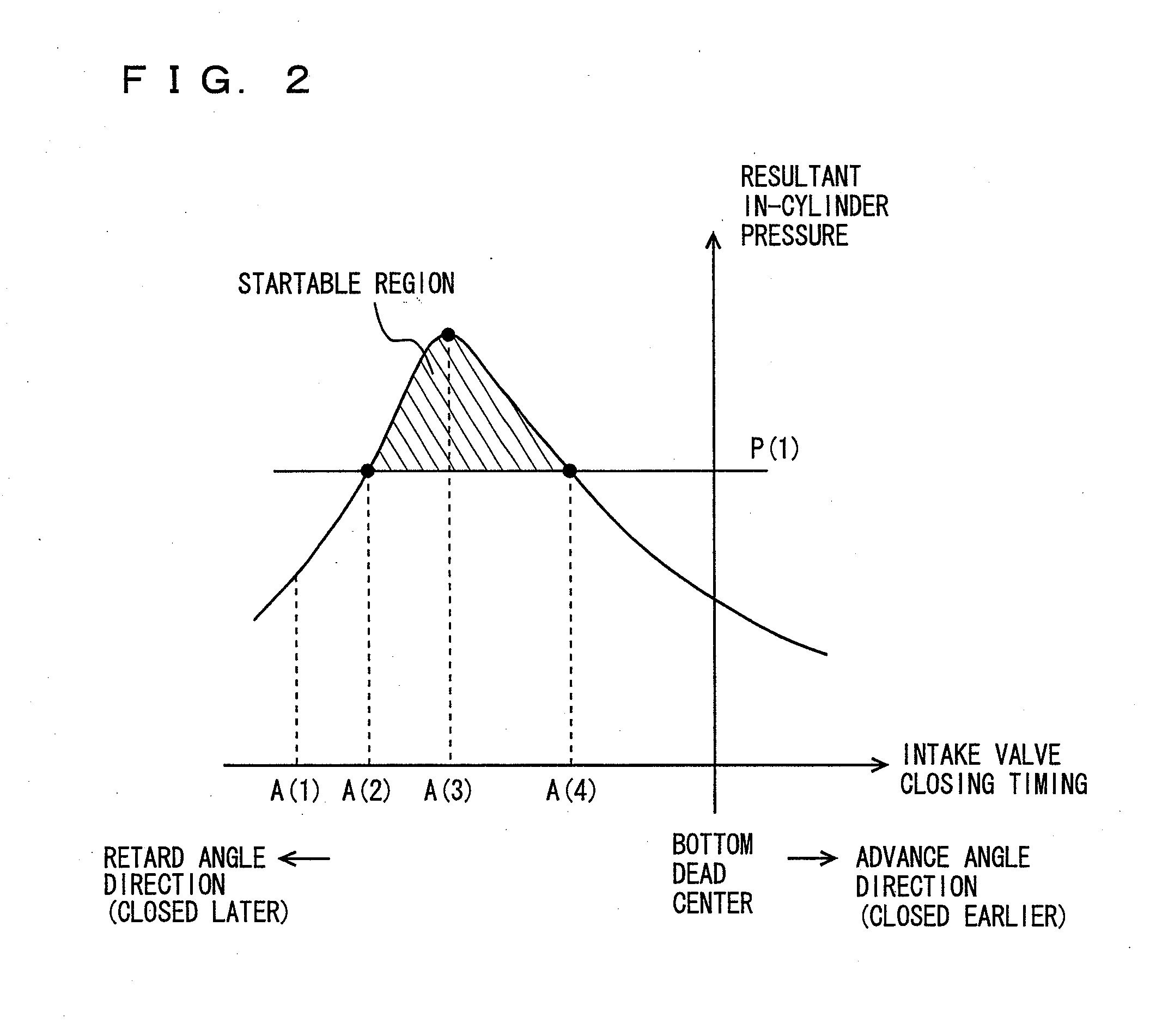
However, in the case where higher priority is given to fuel economy and the valve closing timing is further retarded, a resultant problem is that an in-cylinder pressure with which the internal combustion engine can be started cannot be obtained.
Thus, in the case where higher priority is given to the startability of the internal combustion engine to set the valve closing timing, it could occur that the valve closing timing cannot be set with higher priority given to fuel economy since the variable range of the intake-valve closing timing is limited.
In this case, the in-cylinder pressure with which the internal combustion engine can be started could not be obtained so that the startability is deteriorated.
A resultant problem is therefore that the ensured startability of the internal combustion engine and the improvement of fuel economy cannot be achieved simultaneously.

Method used


Image

  • Internal combustion engine
  • Internal combustion engine
  • Internal combustion engine

Examples


first embodiment

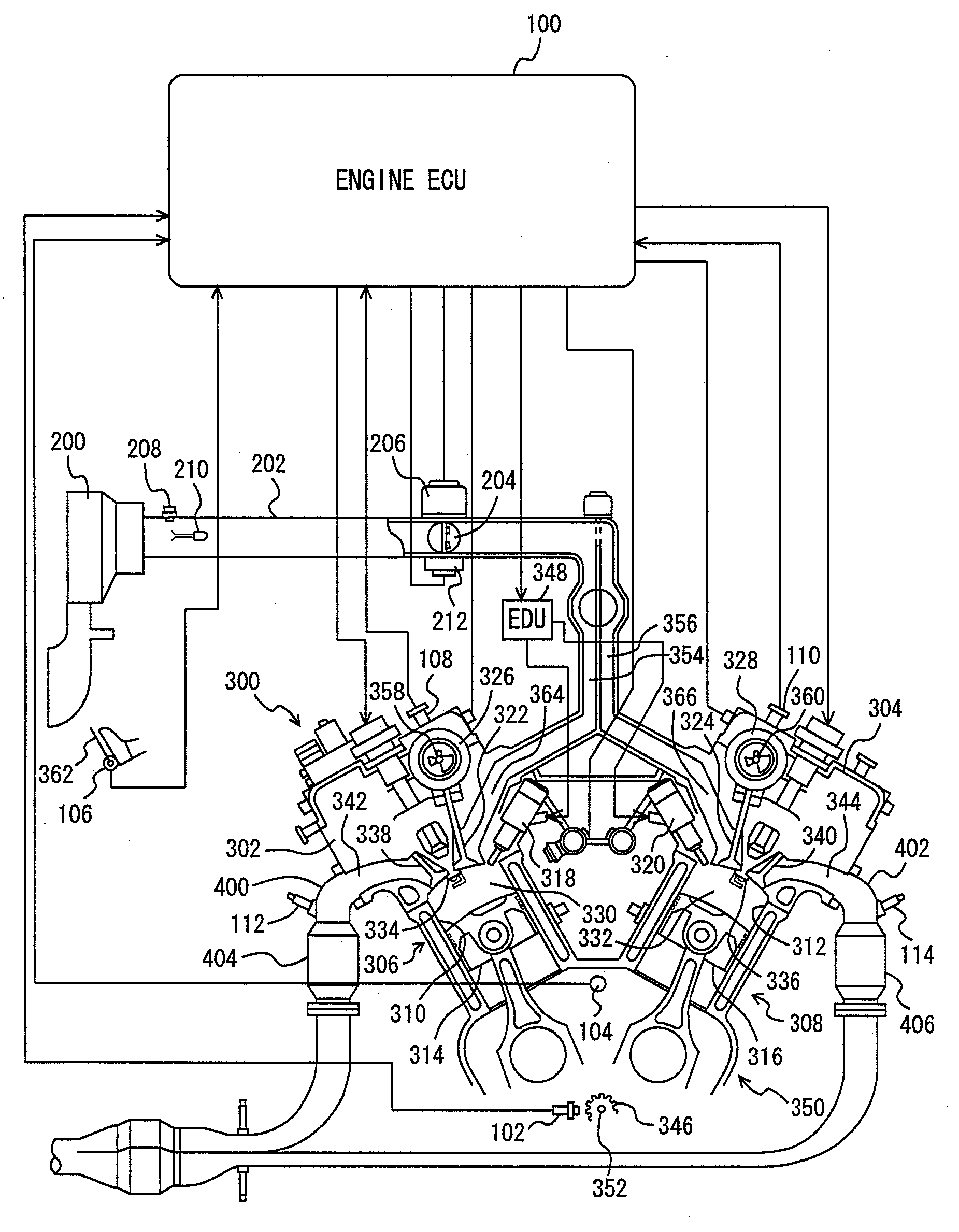
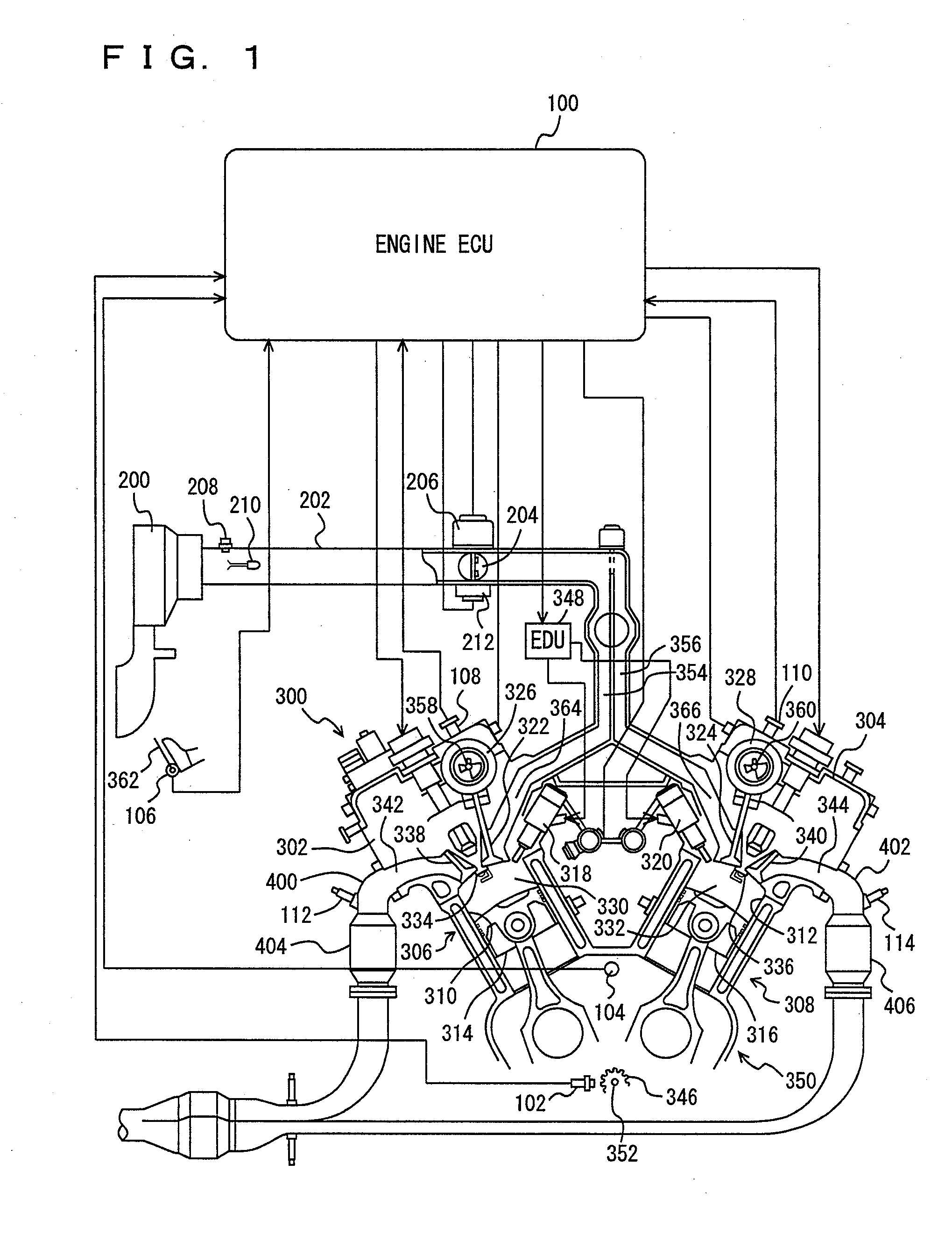
[0037]As shown in FIG. 1, a V-6 engine 300 serving as an internal combustion engine mounted on a vehicle includes a cylinder block 350 having a plurality of cylinders arranged in the shape of V as seen in the direction orthogonal to the plane of the drawing, and a left cylinder head 302 and a right cylinder head 304 each coupled to the top of cylinder block 350. Thus a left group of cylinders 306 and a right group of cylinders 308 are formed. The cylinder groups are each referred to as bank hereinafter. In connection with the present embodiment, although engine 300 is described as a V-6 direct-injection gasoline engine, it is not particularly limited to the engine of this type. As long as the engine has a plurality of banks, the present invention may be applied to horizontally opposed engine or W-engine. Further, the engine here is not limited to the 6-cylinder engine and it may be 4-cylinder or 8-cylinder engine. Furthermore, the present invention may be applied to an engine of the...

second embodiment

[0096]In the following, an internal combustion engine according to a second embodiment of the present invention is described. A vehicle on which the internal combustion engine in the present embodiment is mounted differs in structure from the vehicle on which the internal combustion engine in the first embodiment is mounted in that the former has an intermediate phase fixing mechanism that limits, when engine 300 is stopped, the phase angle of left bank 306 to a phase angle that is substantially equal to the most retarded phase angle of right bank 308. Components other than the above-described one are similar to those of the vehicle on which the internal combustion engine in the first embodiment is mounted. They are denoted by the same reference characters and they function identically. Therefore, the detailed description thereof is not repeated here.

[0097]In the present embodiment, the intermediate phase fixing mechanism is provided to left bank 306 having the most retarded phase a...


PUM


Abstract

An internal combustion engine having a plurality of banks; each having a cylinder provided to said banks comprising: an intake valve provided between said cylinder and an intake manifold a camshaft opening and closing said intake valve by means of mechanical power of said internal combustion engine; and a changing unit changing, according to an operating state of said internal combustion engine a phase angle of said camshaft said phase angle corresponding to a closing timing of said intake valve said banks differing from each other in most retarded phase angle changed by said changing unit.

Description

TECHNICAL FIELD[0001]The present invention relates to an internal combustion engine. In particular, the invention relates to an internal combustion engine having a plurality of banks that differ from each other in valve timing of a most retarded angle.BACKGROUND ART[0002]To an internal combustion engine mounted on a vehicle, a variable valve timing mechanism has conventionally been provided. The variable valve timing mechanism for example continuously and variably controls opening / closing timing of an intake valve by means of oil-hydraulic drive under electronic control so as to improve torque at low to medium speed, fuel economy and emission performance. The closing timing of the intake valve is set with higher priority given to startability when the internal combustion engine is started.[0003]For example, Japanese Patent Laying-Open No. 06-323168 discloses a control apparatus for an internal combustion engine promoting atomization of injected fuel at the start of the internal comb...

Claims


Application Information

Patent Timeline
Patent Type & Authority Applications(United States)
IPC IPC(8): F02D41/00F01L1/34
CPCF01L1/053F01L1/34F01L13/00F02B75/22F02D13/0238F02D13/0261Y02T10/18F02D41/0082F02D41/062F02D2041/001F02N19/004Y02T10/42F02D41/0002Y02T10/12Y02T10/40F02D41/06
Inventor NISHIMURA, TAICHI
Owner TOYOTA JIDOSHA KK
Learn More