Gas Turbine Burner and Method of Mixing Fuel and Air in a Swirling Area of a Gas Turbine Burner

a gas turbine burner and swirling technology, which is applied in the direction of burners, hot gas positive displacement engine plants, combustion processes, etc., can solve the problems of environmental damage, take considerable effort to keep pollutants as low as possible, etc., and achieve the effects of reducing the formation of hot spots, improving air mixing, and reducing the emission of nitrous oxid

Inactive Publication Date: 2010-09-09
SIEMENS AG
View PDF9 Cites 12 Cited by
  • Summary
  • Abstract
  • Description
  • Claims
  • Application Information

AI Technical Summary

Benefits of technology

[0016]By injecting additional air into the streaming medium additional turbulence can be formed which helps to improve the mixing of air and fuel and the homogeneity of the mixture. This in turn reduces the formation of hot spots which are the main areas of nitrous oxide formation. As a consequence, reduction of the number and the te

Problems solved by technology

However, burning the fuel leads to a number of undesired pollutants in the exhaust gas which can cause da

Method used


Image

  • Gas Turbine Burner and Method of Mixing Fuel and Air in a Swirling Area of a Gas Turbine Burner
  • Gas Turbine Burner and Method of Mixing Fuel and Air in a Swirling Area of a Gas Turbine Burner
  • Gas Turbine Burner and Method of Mixing Fuel and Air in a Swirling Area of a Gas Turbine Burner

Examples


Embodiment Construction

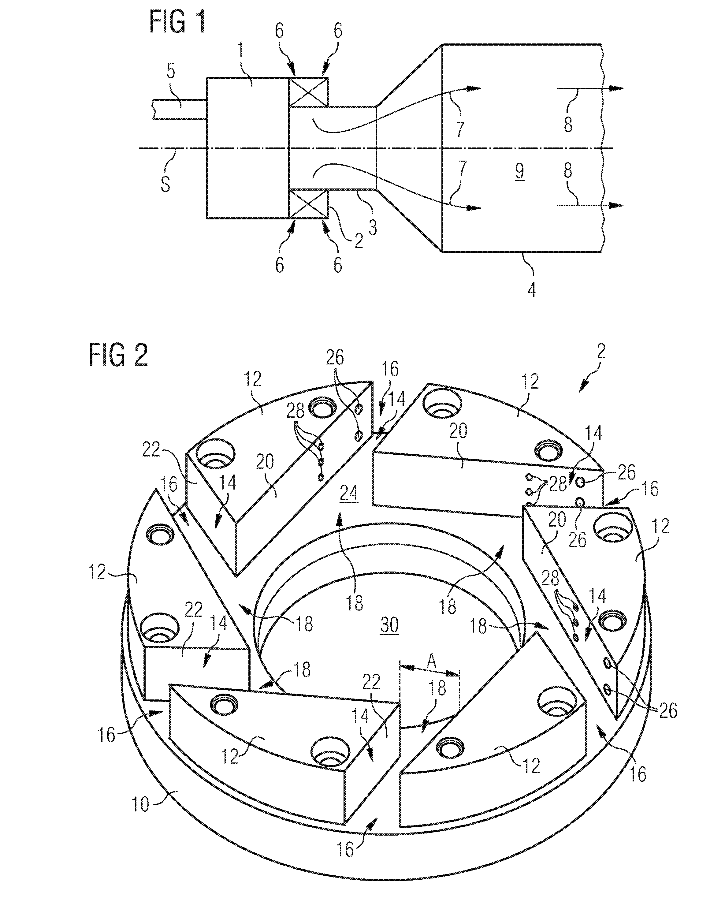
[0027]FIG. 1 shows a longitudinal section through a burner and combustion chamber assembly for a gas turbine engine. A burner head 1 with a swirler for mixing air and fuel is attached to an upstream end of a combustion chamber comprising, in flow series, a combustion pre-chamber 3 and a combustion main chamber 4. The burner and the combustion chamber assembly show rotational symmetry about a longitudinally symmetry axis S. A fuel conduit 5 is provided for leading a gaseous or liquid fuel to the burner which is to be mixed with in-streaming air in the swirler 2. The fuel air mixture 7 is then led towards the primary combustion zone 9 where it is burnt to form hot, pressurised exhaust gases streaming in a direction 8 indicated by arrows to a turbine of the gas turbine engine (not shown).

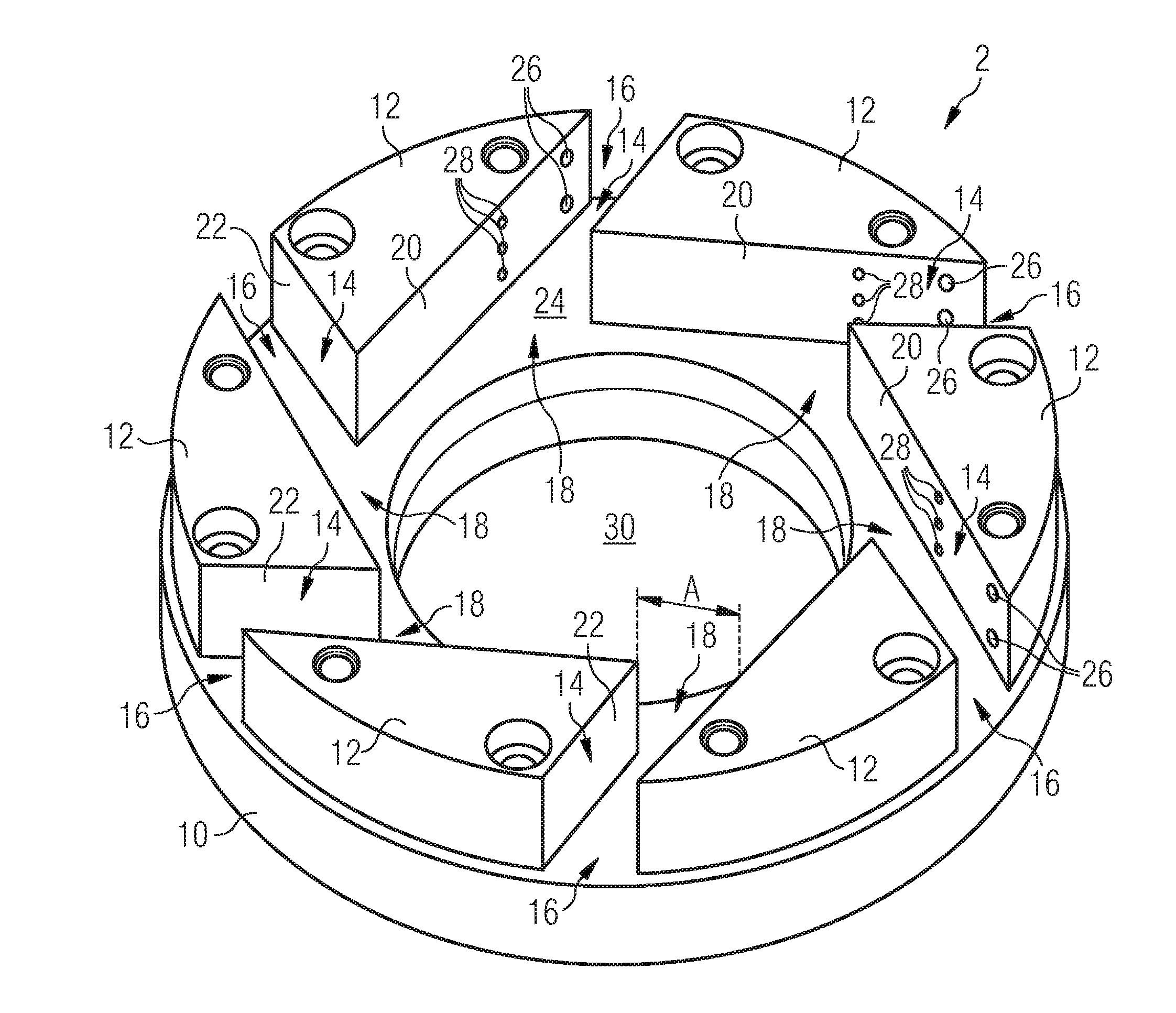
[0028]The swirler 2 is shown in detail in FIG. 2. It comprises a swirler vane support 10 carrying six swirler vanes 12. The swirler vanes 12 can be fixed to the burner head 1 with their sides opposite ...


PUM


Abstract

A gas turbine burner, comprising at least one swirler, the swirler having at least one air inlet opening, at least one air outlet opening positioned downstream to the air inlet opening and at least one swirler air passage extending from the at least one air inlet opening to the at least one air outlet opening which is delimited by swirler air passage walls; a fuel injection system which comprises fuel injection openings arranged in at least one swirler air passage wall so as to inject fuel into the swirler air passage; and an air injection system which comprises air injection openings arranged in at least one swirler air passage wall and positioned downstream of the fuel injection openings for injecting air into the swirler air passage.

Description

CROSS REFERENCE TO RELATED APPLICATIONS[0001]This application is the US National Stage of International Application No. PCT / EP2006 / 070236, filed Dec. 28, 2006 and claims the benefit thereof. The International Application claims the benefits of European application No. 06003056.6 filed Feb. 15, 2006, both of the applications are incorporated by reference herein in their entirety.FIELD OF INVENTION[0002]The present invention relates to a gas turbine burner having an air inlet duct and at least one swirler disposed in said air inlet duct. In addition, the invention relates to a method of mixing fuel and air in a swirling area of a gas turbine burner.BACKGROUND OF THE INVENTION[0003]In a gas turbine burner a fuel is burned to produce hot pressurised exhaust gases which are then fed to a turbine stage where they, while expanding and cooling, transfer momentum to turbine blades thereby imposing a rotational movement on a turbine rotor. Mechanical power of the turbine rotor can then be use...

Claims


Application Information

Patent Timeline
IPC IPC(8): F23R3/14F23R3/28F23C7/00
CPCF23C7/004F23C2900/07001F23R3/286F23D2900/14701F23D2900/14021
Inventor WILBRAHAM, NIGEL
Owner SIEMENS AG
Why Eureka
Try Eureka